Textile dust removal device and using method thereof

A technology of dust removal device and main body, applied in the direction of separation method, use of liquid separation agent, chemical instrument and method, etc., can solve the problems of low air filtration efficiency, achieve good filtration effect and improve efficiency

Inactive Publication Date: 2020-12-04
黄时成
View PDF0 Cites 0 Cited by
  • Summary
  • Abstract
  • Description
  • Claims
  • Application Information

AI Technical Summary

Problems solved by technology

[0004] The purpose of the present invention is to solve the problem of low air filtration efficiency of existing devices on multiple horizontal planes, and propose a textile dust removal device and its use method

Method used


Image

  • Textile dust removal device and using method thereof
  • Textile dust removal device and using method thereof
  • Textile dust removal device and using method thereof

Examples


Embodiment 1

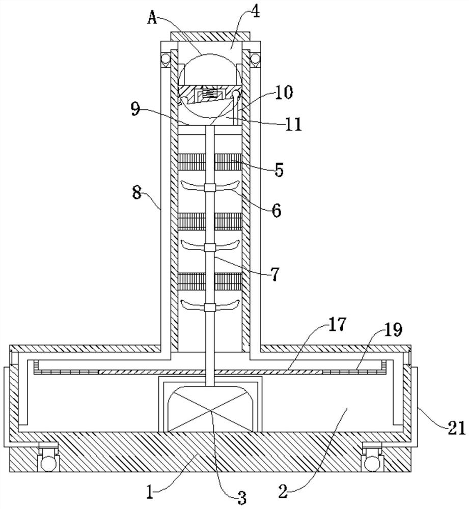
[0032] refer to Figure 1-10 , a textile dedusting device and its use method, comprising a main body 1, a water chamber 2 is provided at the lower end of the main body 1, a drive motor 3 is connected in the water chamber 2, a partition block 34 is slidably connected to the upper end of the main body 1, and the partition block 34 is connected to the main body 1 The upper end forms a suction chamber 4, and the suction chamber 4 is symmetrically connected with a water suction pipe 8, and the end of the water suction pipe 8 away from the water suction chamber 4 is connected with the water chamber 2, and the output end of the driving motor 3 in the water suction pipe 8 is fixedly connected with a rotating shaft 7, and the rotating shaft 7 is fixedly connected with multiple groups of rotating blades 6, and the main body 1 is connected with multiple groups of first filter screens 5, the first filter screen 5 is matched with the rotating blades 6, and the top of the rotating shaft 7 is...

Embodiment 2

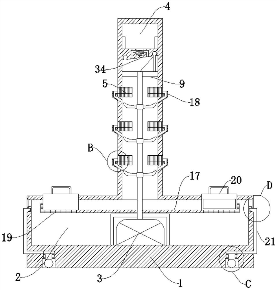
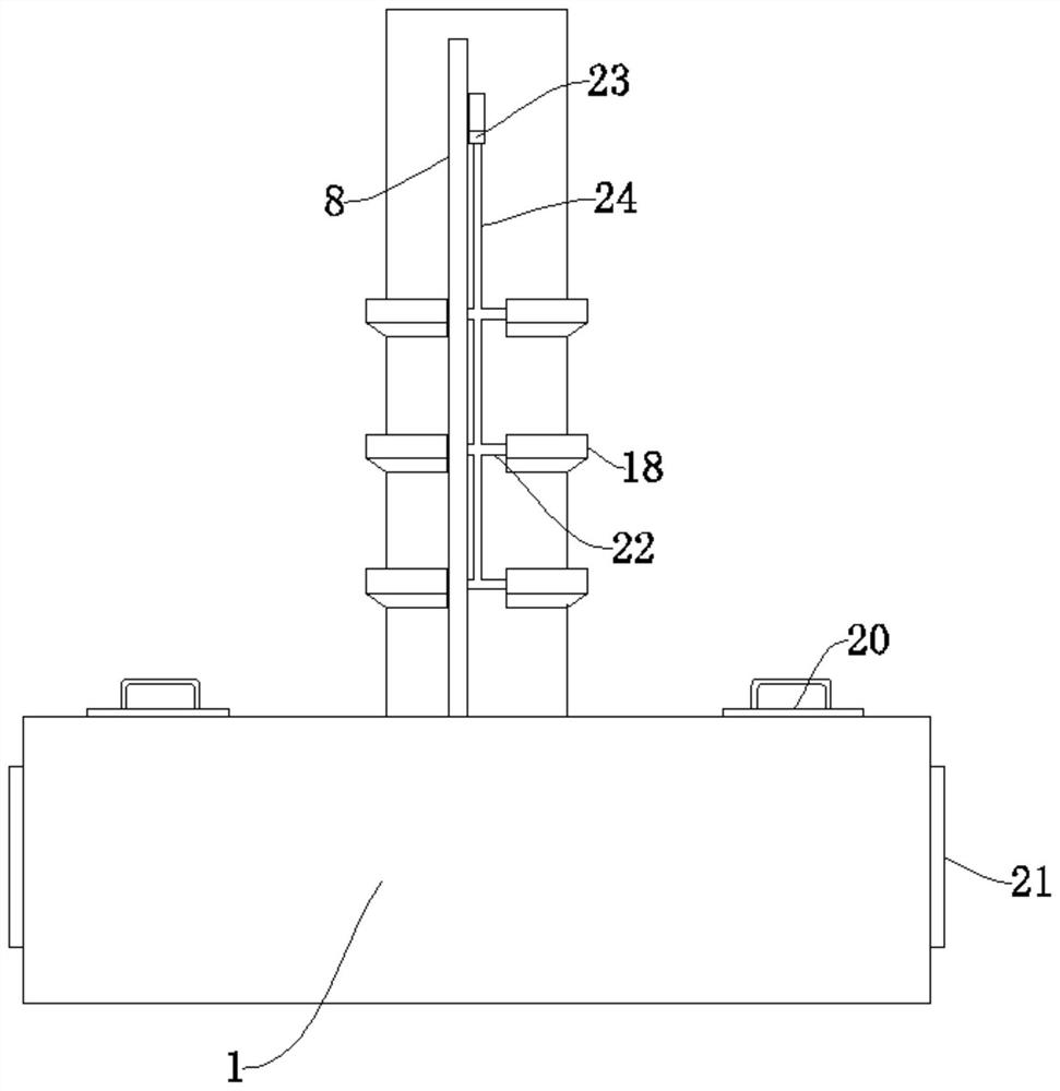
[0036] refer to Figure 1-10 , a textile dedusting device and its use method are basically the same as in Embodiment 1, furthermore: the main body 1 is fixedly connected with multiple sets of first baffles 18 near the first filter screen 5, and the outer wall of the upper end of the main body 1 is slidably connected There are multiple groups of scraping bars 22, the scraping bars 22 are matched with the first baffle plate 18 and the first filter screen 5, the partition block 34 is symmetrically fixedly connected with a slider 23, the slider 23 is slidably connected with the main body 1, and the slider 23 The lower end is fixedly connected with a pull rod 24, and the pull rod 24 is fixedly connected with the scraper rod 22. When the partition block 34 moves up and down, the slider 23 is driven to move up and down, and the pull rod 24 is used to move the scraper rod 22 up and down, and the first filter screen 5 is moved up and down. Sticky textile fibers are scraped into the fir...

Embodiment 3

[0038] refer to Figure 1-10 , a textile dedusting device and its use method are basically the same as in Embodiment 1, furthermore: the lower end of the rotating shaft 7 is fixedly connected with a rotating disc 17, and the side of the rotating disc 17 away from the rotating shaft 7 is fixedly connected with a second filter screen 19 , the main body 1 is slidably connected with a collection box 20, the collection box 20 is attached to the second filter screen 19, the used water falls on the rotating disk 17, and due to the rotation of the rotating disk 17, the rotating disk 17 will be rotated under the action of centrifugal force. The water and impurities on the filter are thrown into the second filter screen 19, and the water leaks into the water chamber 2 from the second filter screen 19. Since the collection box 20 is attached to the second filter screen 19, the water on the second filter screen 19 is Impurities are scraped into the collection box, so that the impurities i...


PUM


Abstract

The invention discloses a textile dust removal device and a using method thereof, and belongs to the technical field of textile dust removal. The textile dust removal device comprises a main body, a water cavity is formed in the lower end of the main body, a driving motor is connected into the water cavity, a separation block is slidably connected to the upper end of the main body, a water pumpingcavity is formed by the separation block and the upper end of the main body, and water suction pipes are symmetrically connected to the water pumping cavity; and the end, away from the water pumpingcavity, of each water suction pipe is connected with the water cavity, and the output end of a driving motor in each water suction pipe is fixedly connected with a rotating shaft. Through the water cavity, the driving motors, the water pumping cavity, rotating fan blades, the rotating shaft, a rotating frame, a rotating rod and the like, air in multiple horizontal planes is absorbed and filtered,the filtering effect is improved, fibers on a first filter screen are removed through a scraping rod and a sliding block, and the filtering effect is improved. And through a rotating disc and a collecting box, the purpose of recycling impurities in the main body is achieved.

Description

technical field [0001] The invention relates to the technical field of textile dust removal, in particular to a textile dust removal device and a use method thereof. Background technique [0002] The original meaning of textile is taken from the general term of spinning and weaving, but with the continuous development and improvement of the textile knowledge system and subject system, especially after the emergence of non-woven textile materials and three-dimensional composite weaving technologies, textile is not only the traditional spinning and weaving Weaving also includes non-woven technology, three-dimensional weaving technology, electrostatic nano-netting technology, etc.; [0003] When weaving, it is inevitable that there will be some lint wastes, which are easy to float in the air. If they are inhaled by the human body, they will cause serious damage to the human respiratory system. Therefore, it is necessary to treat the textile fibers in the air. Yes, but the exis...

Claims


Application Information

Patent Timeline
Patent Type & Authority Applications(China)
IPC IPC(8): B01D47/00B01D29/58B01D29/64
CPCB01D29/58B01D29/6484B01D47/00
Inventor 黄时成
Owner 黄时成
Why Eureka
Try Eureka