
Stainless steel basin polishing equipment

A stainless steel and equipment technology, applied in the field of stainless steel basin polishing equipment, can solve problems such as low efficiency and time-consuming

Active Publication Date: 2020-12-04
南京市淑先科技有限公司
View PDF9 Cites 9 Cited by
  • Summary
  • Abstract
  • Description
  • Claims
  • Application Information

AI Technical Summary

Problems solved by technology

[0005]In order to overcome the need to continuously place the product in the equipment manually, and then start the device for grinding and polishing, the entire blanking process requires manual operation, which takes a long time Many, low efficiency, the purpose of the present invention is to provide a stainless steel basin polishing equipment that can quickly polish the stainless steel basin and can perform grinding and polishing in batches

Method used


Image

  • Stainless steel basin polishing equipment
  • Stainless steel basin polishing equipment
  • Stainless steel basin polishing equipment

Examples


Embodiment 1

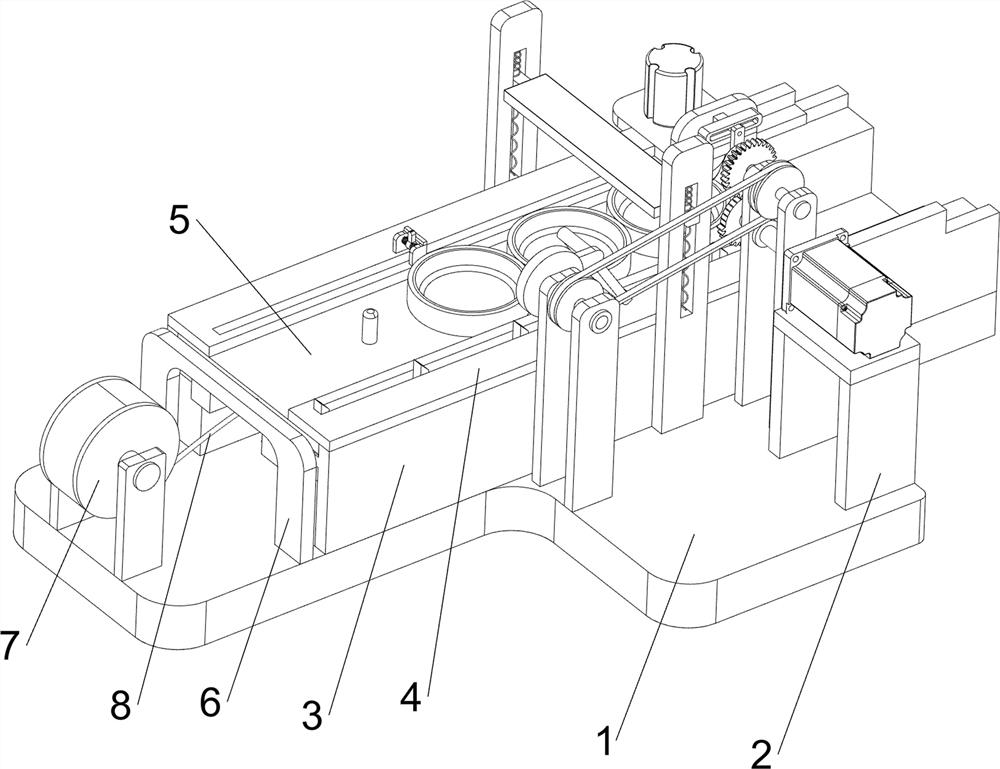
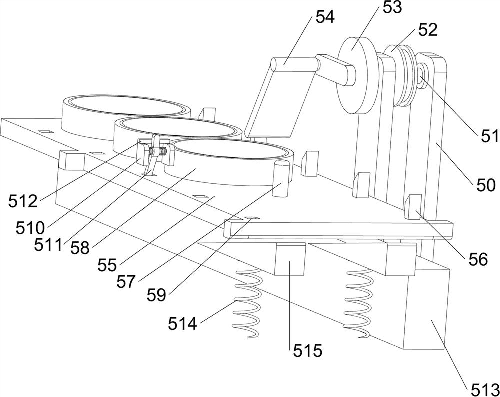
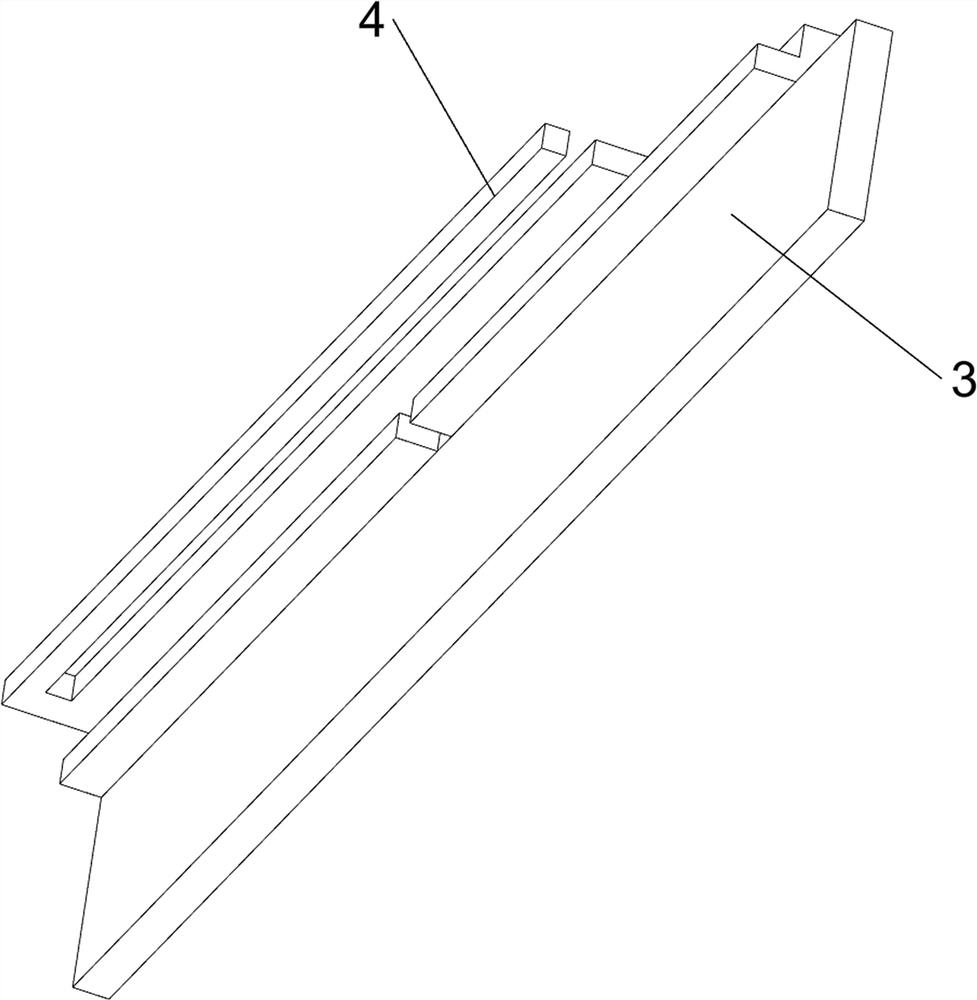
[0022] A stainless steel basin polishing equipment, such as figure 1 and Figure 4 As shown, it includes a base plate 1, a polishing mechanism 2, a support member 3, a first baffle plate 4, a propulsion mechanism 5, a second baffle plate 6, a take-up wheel 7 and a pull wire 8, and a polishing mechanism 2 is provided on the right front side of the upper part of the bottom plate 1. , the upper part of the bottom plate 1 is provided with a symmetrical front and rear supporting member 3, the supporting members 3 on the front and rear sides are respectively provided with a first baffle plate 4, the supporting members 3 on the front and rear sides are provided with a propulsion mechanism 5, and the left side of the upper part of the bottom plate 1 is provided with There is a second baffle plate 6, the second baffle plate 6 is located on the left side of the support member 3 on the front and rear sides, and a take-up wheel 7 is arranged in the middle of the left side of the upper par...

Embodiment 2

[0025] On the basis of Example 1, such as Figure 2-3 As shown, the polishing mechanism 2 includes a support frame 20, a first servo motor 21, a first bearing seat 22, a missing gear 23, a first rotating shaft 24, a full gear 25, a first rotating rod 26, a connecting block 27, and a guide block 28 , the first spring 29, the lifting rod 210, the connector 211, the second servo motor 212 and the grinding block 213, the upper right side of the base plate 1 is provided with a support frame 20, the support frame 20 top is provided with the first servo motor 21, the base plate 1 top The front and rear sides of the right side are symmetrically provided with a first bearing seat 22, and the first bearing seats 22 on the front and rear sides are located on the rear side of the support frame 20, and the output shaft of the first servo motor 21 passes through the first bearing seats 22 on the front and rear sides. The output shaft of the first servo motor 21 is provided with a missing ge...


PUM


Abstract

The invention relates to polishing equipment, in particular to stainless steel basin polishing equipment. The aim is to provide the stainless steel basin polishing equipment which can be used for rapidly grinding and polishing stainless steel basins and can achieve batch grinding and polishing. The stainless steel basin polishing equipment comprises a bottom plate, a polishing mechanism, supporting pieces and first baffles; the front side of the bottom plate is provided with a protruding position; the polishing mechanism is arranged at the front right side of the upper portion of the bottom plate; the supporting pieces are arranged at the upper portion of the bottom plate in a front-back symmetrical manner; and the first baffles are arranged at the supporting pieces at the front side and the rear side correspondingly. The stainless steel basin polishing equipment achieves the effects that the stainless steel basins can be rapidly ground and polished and can be ground and polished in batches; and a connecting piece moves up and down, a grinding block can be driven to move up and down accordingly, and therefore the grinding block can continuously and rapidly grind and polish the stainless steel basins in a disc.

Description

technical field [0001] The invention relates to a polishing device, in particular to a stainless steel basin polishing device. Background technique [0002] Stainless steel, like many other metals, will be oxidized and rusted when it is touched by hand or exposed to the air and affected by the environment. In addition, the surface of stainless steel workpieces is processed by machining such as welding, stamping, crimping, heat treatment and other processes to form a layer of black oxidation deterioration. At the same time, many tiny burrs and sharp-edged burrs, which are visible and invisible to the naked eye, are formed. Therefore, people use various methods to mirror-polish metal surfaces such as stainless steel. [0003] Existing polishing equipment, such as the Chinese patent whose patent notification number is CN106625161B discloses a grinding and polishing device and a grinding and polishing method, including a support part; a grinding and polishing part is used for gr...

Claims


Application Information

Patent Timeline
Patent Type & Authority Applications(China)
IPC IPC(8): B24B27/033B24B5/08B24B29/04B24B41/06B24B41/00B24B47/12B24B47/16
CPCB24B27/033B24B5/08B24B29/04B24B41/06B24B41/005B24B47/12B24B47/16
Inventor 林灿燕
Owner 南京市淑先科技有限公司
Learn More