Metal butterfly valve

A butterfly valve and metal technology, which is applied in the field of butterfly valve improvement and invention, can solve the problem that the valve cannot maintain sealing, etc., and achieve the effects of increased sealing specific pressure, good sealing performance, and convenient installation

Inactive Publication Date: 2020-12-04
李祥庆
View PDF5 Cites 2 Cited by
  • Summary
  • Abstract
  • Description
  • Claims
  • Application Information

AI Technical Summary

Problems solved by technology

[0003] The existing butterfly valve with triple eccentric structure only has a good one-way sealing performance when in use. If the medium enters the inner cavity of the butterfly valve from the inlet side of the valve, when the valve is closed, the medium on the inlet side pushes the butterfly plate to press the valve seat. The sealing specific pressure at the sealing surface increases, which has good sealing performance. If the medium enters the inner cavity of the butterfly valve from the outlet side of the valve, the medium on the outlet side will give a reverse force to the butterfly plate, so that the sealing ratio at the sealing surface If the pressure is reduced, the valve cannot maintain a tight seal

Method used


Image

  • Metal butterfly valve
  • Metal butterfly valve
  • Metal butterfly valve

Examples


Embodiment Construction

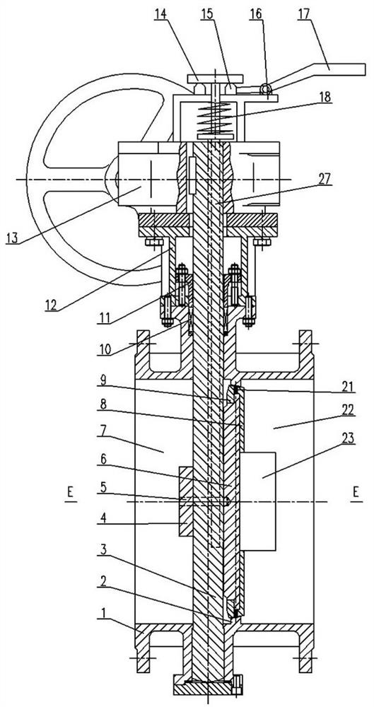
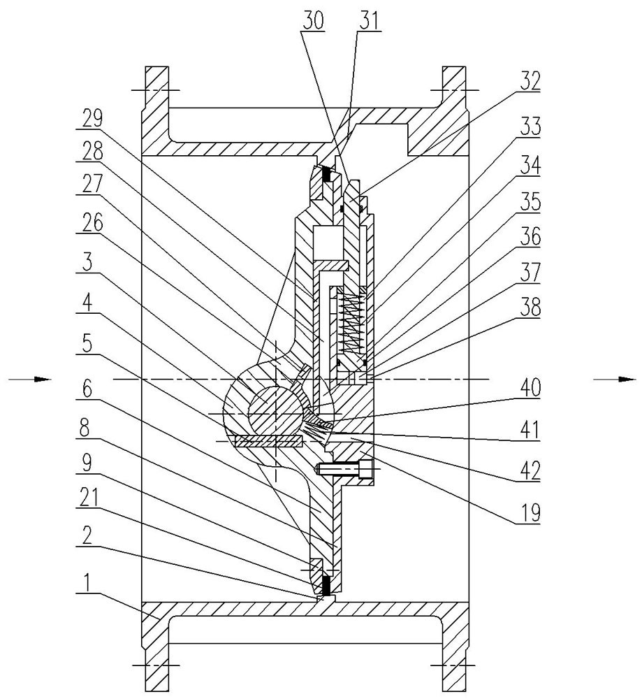
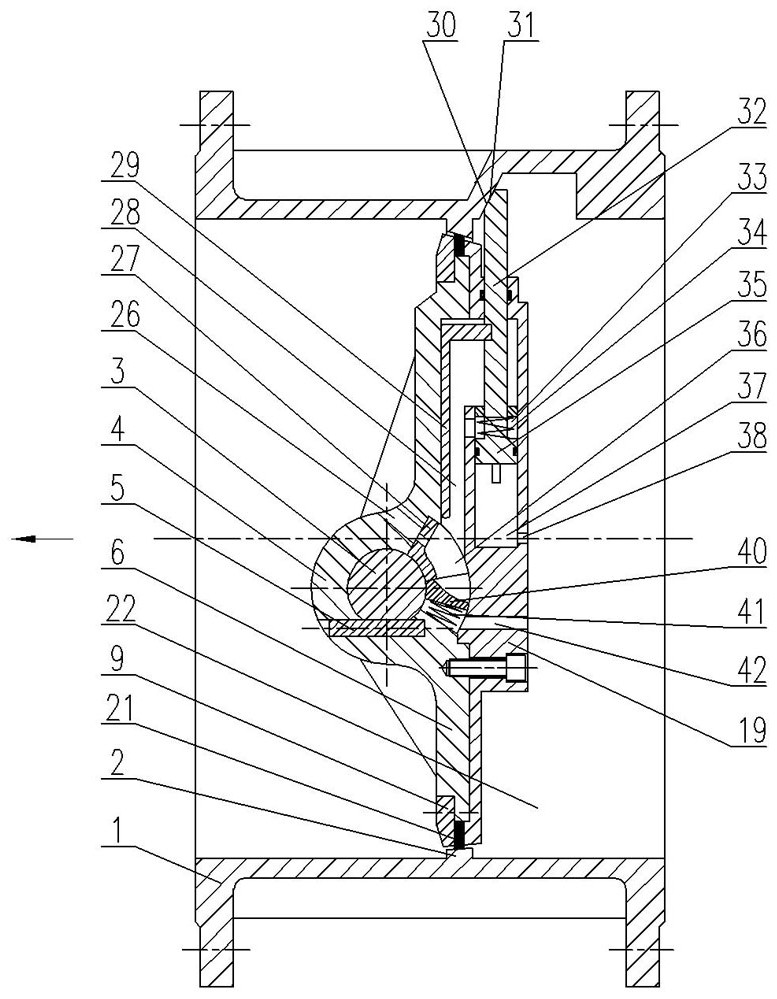
[0017] Accompanying drawing has shown structure of the present invention, further illustrates its relevant details below again in conjunction with accompanying drawing. In this embodiment, the metal butterfly valve includes a valve body 1 and a valve stem 3, and the inner cavity of the valve body 1 is provided with a sealingly fitted butterfly plate 6 and a valve seat 2 as well as valves located on the left and right sides of the butterfly plate 6. The inlet cavity 7 and the outlet cavity 22, and the butterfly plate 6 can be rotated eccentrically, and the sealing surface of the corresponding butterfly plate 6 and the valve seat 2 is a matching inclined surface, and the valve stem 3 is rotatably installed on the valve body 1, and A packing 10 is provided between the valve stem 3 and the upper end of the valve body 1, and the packing 10 is pressed by a gland 11, and the upper end of the valve stem 3 is connected to the driving device 13 by transmission, and the driving device 13 ...


PUM


Abstract

The invention discloses a metal butterfly valve. The metal butterfly valve comprises a valve body and a valve rod, wherein a butterfly plate, a valve seat, an inlet cavity and an outlet cavity are arranged in an inner cavity of the valve body, the butterfly plate and the valve seat are matched in a sealing mode, the inlet cavity and the outlet cavity are located on the left side and the right sideof the butterfly plate respectively, the butterfly plate is eccentrically and rotationally arranged, the corresponding sealing face of the butterfly plate and the valve seat is a matched slope, the valve rod is arranged on the the valve body in a penetrating mode, the upper end of the valve rod is in transmission connection with a driving device, and the lower section of the valve rod is in transmission connection with the butterfly plate. The metal butterfly valve is characterized in that a leakage-proof device is arranged on the plate face, located on the outlet side, of the butterfly plateand comprises a box body, the box body is internally provided with a piston, a plug rod, a piston cavity, a spring cavity, a vent groove, an ejector rod, a first pressure guide hole and a second pressure guide hole, the outer end of the plug rod is movably arranged on the box body in the penetrating mode, a rod slope is arranged at the outer end of the piston rod, the inner end of the piston rodis connected with the piston, the piston is movably arranged in the piston cavity, and the piston cavity communicates with the outlet cavity through the first pressure guide hole; a body slope is arranged on the left side wall of the inner cavity of the valve body, and when the plug rod stretches out of the box body, the rod slope is in press fit with the body slope.

Description

technical field [0001] The invention relates to an improved invention of a butterfly valve, in particular to an improved invention of a metal butterfly valve. Background technique [0002] Butterfly valves are widely used in petroleum refining, long-distance pipelines, chemical industry, papermaking, pharmaceuticals, water conservancy, electric power, municipal, steel and other industries. [0003] The existing butterfly valve with triple eccentric structure only has a good one-way sealing performance when in use. If the medium enters the inner cavity of the butterfly valve from the inlet side of the valve, when the valve is closed, the medium on the inlet side pushes the butterfly plate to press the valve seat. The sealing specific pressure at the sealing surface increases, which has good sealing performance. If the medium enters the inner cavity of the butterfly valve from the outlet side of the valve, the medium on the outlet side will give a reverse force to the butterfl...

Claims


Application Information

Patent Timeline
Patent Type & Authority Applications(China)
IPC IPC(8): F16K1/22F16K1/226F16K1/228F16K39/02
CPCF16K1/22F16K1/2261F16K1/2285F16K39/028
Inventor 李祥庆
Owner 李祥庆
Why Eureka
Try Eureka