Optical image capturing system
An optical imaging system and light technology, applied in optics, optical components, instruments, etc., can solve the problems of impact, miniaturization, etc., and achieve good imaging quality
- Summary
- Abstract
- Description
- Claims
- Application Information
AI Technical Summary
Problems solved by technology
Method used
Image

Examples
Embodiment 1
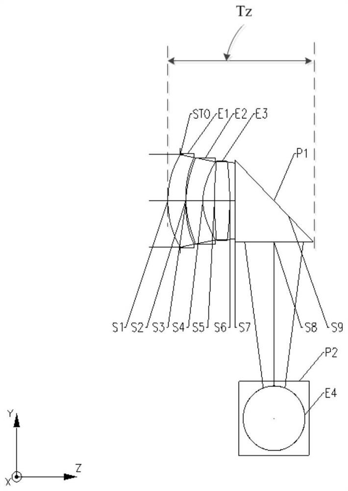
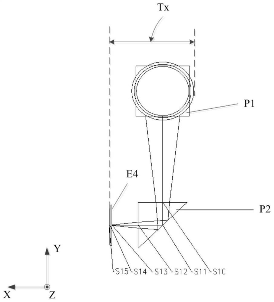
[0066] Refer to the following Figure 1A to Figure 2D An optical imaging system according to Embodiment 1 of the present application is described. Figure 1A A schematic structural diagram of the optical imaging system on the Y-Z plane according to Embodiment 1 of the present application is shown. Figure 1B A schematic structural diagram of the optical imaging system on the Y-X plane according to Embodiment 1 of the present application is shown.
[0067] Such as Figure 1A with Figure 1B As shown, the optical imaging system sequentially includes from the object side along the first direction Z: a stop STO, a first lens E1 , a second lens E2 , a third lens E3 and a first prism P1 . The incident light passes through the stop STO, the first lens E1 , the second lens E2 and the third lens E3 from the object side in order from the first direction Z to the first prism P1 . The optical imaging system sequentially includes a first prism P1 and a second prism P2 along the second ...
Embodiment 2
[0080] Refer to the following Figure 3A to Figure 4D An optical imaging system according to Embodiment 2 of the present application is described. In this embodiment and the following embodiments, for the sake of brevity, descriptions similar to those in Embodiment 1 will be omitted. Figure 3A A schematic structural diagram of the optical imaging system on the Y-Z plane according to Embodiment 2 of the present application is shown. Figure 3B A schematic structural diagram of the optical imaging system on the Y-X plane according to Embodiment 2 of the present application is shown.
[0081] Such as Figure 3A with Figure 3B As shown, the optical imaging system sequentially includes from the object side along the first direction Z: a stop STO, a first lens E1 , a second lens E2 , a third lens E3 and a first prism P1 . The incident light passes through the stop STO, the first lens E1 , the second lens E2 and the third lens E3 from the object side in order from the first d...
Embodiment 3
[0092] Refer to the following Figure 5A to Figure 6D An optical imaging system according to Embodiment 3 of the present application is described. Figure 5A A schematic structural view of the optical imaging system on the Y-Z plane according to Embodiment 3 of the present application is shown. Figure 5B A schematic structural diagram of the optical imaging system on the Y-X plane according to Embodiment 3 of the present application is shown.
[0093] Such as Figure 5A with Figure 5B As shown, the optical imaging system sequentially includes from the object side along the first direction Z: a stop STO, a first lens E1 , a second lens E2 , a third lens E3 and a first prism P1 . The incident light passes through the stop STO, the first lens E1 , the second lens E2 and the third lens E3 from the object side in order from the first direction Z to the first prism P1 . The optical imaging system sequentially includes a first prism P1 and a second prism P2 along the second d...
PUM
 Abstract
Description
Claims
Application Information
 - R&D
- Intellectual Property
- Life Sciences
- Materials
- Tech Scout
- Unparalleled Data Quality
- Higher Quality Content
- 60% Fewer Hallucinations
Browse by: Latest US Patents, China's latest patents, Technical Efficacy Thesaurus, Application Domain, Technology Topic, Popular Technical Reports.
© 2025 PatSnap. All rights reserved.Legal|Privacy policy|Modern Slavery Act Transparency Statement|Sitemap|About US| Contact US: help@patsnap.com