Electronic-type current-voltage-combined transformer for GIS (gas insulated switchgear)

A technology of combining transformers, current and voltage, applied in the direction of inductors, voltage dividers, transformers, etc., can solve the problem of electronic transformers without dual voltage sensing heads

Inactive Publication Date: 2013-07-17
XUJI GRP +1
View PDF7 Cites 17 Cited by
  • Summary
  • Abstract
  • Description
  • Claims
  • Application Information

AI Technical Summary

Problems solved by technology

[0004] The purpose of the present invention is to provide an electronic current-voltage combined transformer for GIS that can provide dual sensing heads,

Method used


Image

  • Electronic-type current-voltage-combined transformer for GIS (gas insulated switchgear)
  • Electronic-type current-voltage-combined transformer for GIS (gas insulated switchgear)
  • Electronic-type current-voltage-combined transformer for GIS (gas insulated switchgear)

Examples


Embodiment Construction

[0016] The present invention will be described in further detail below in conjunction with the accompanying drawings.

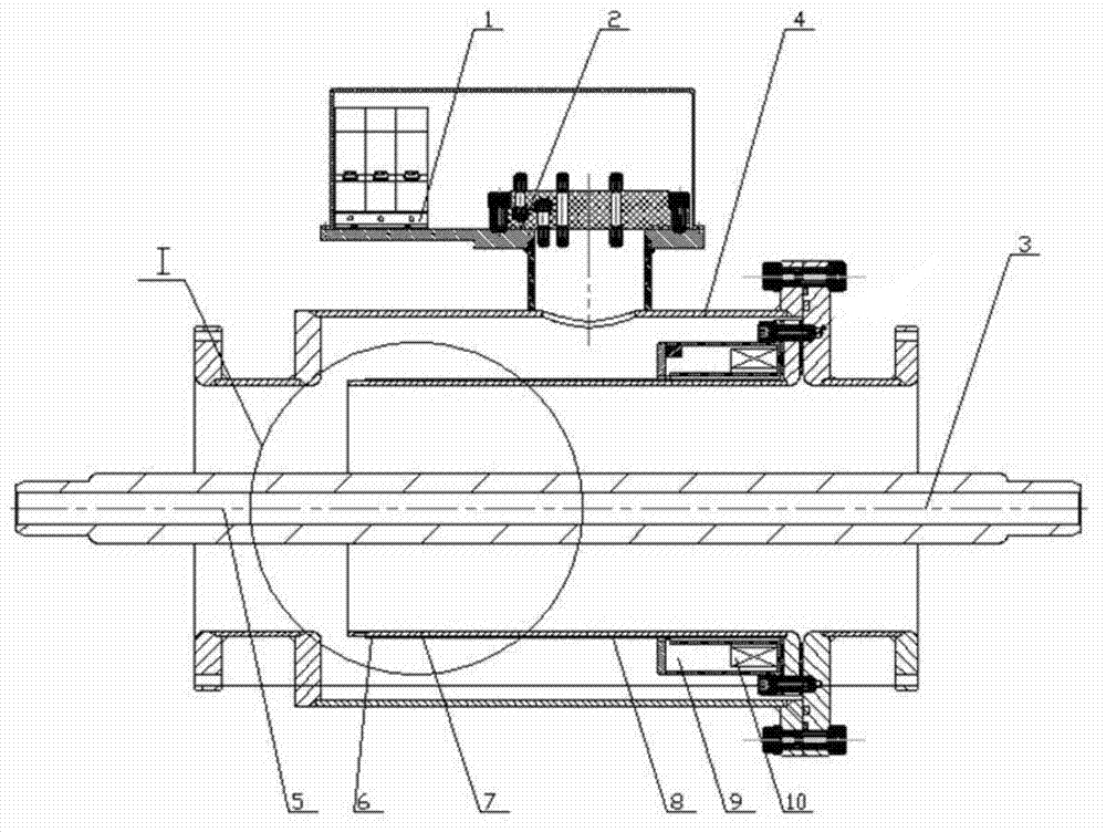
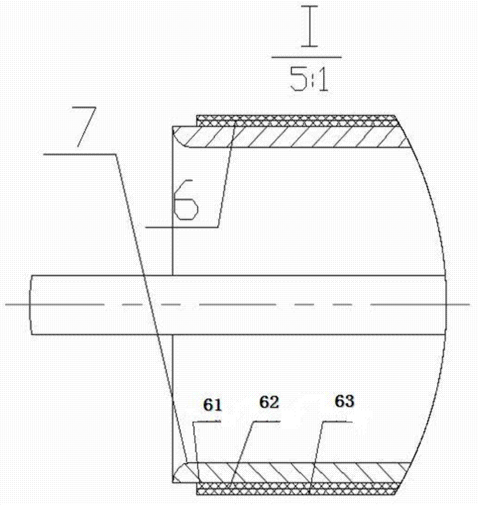
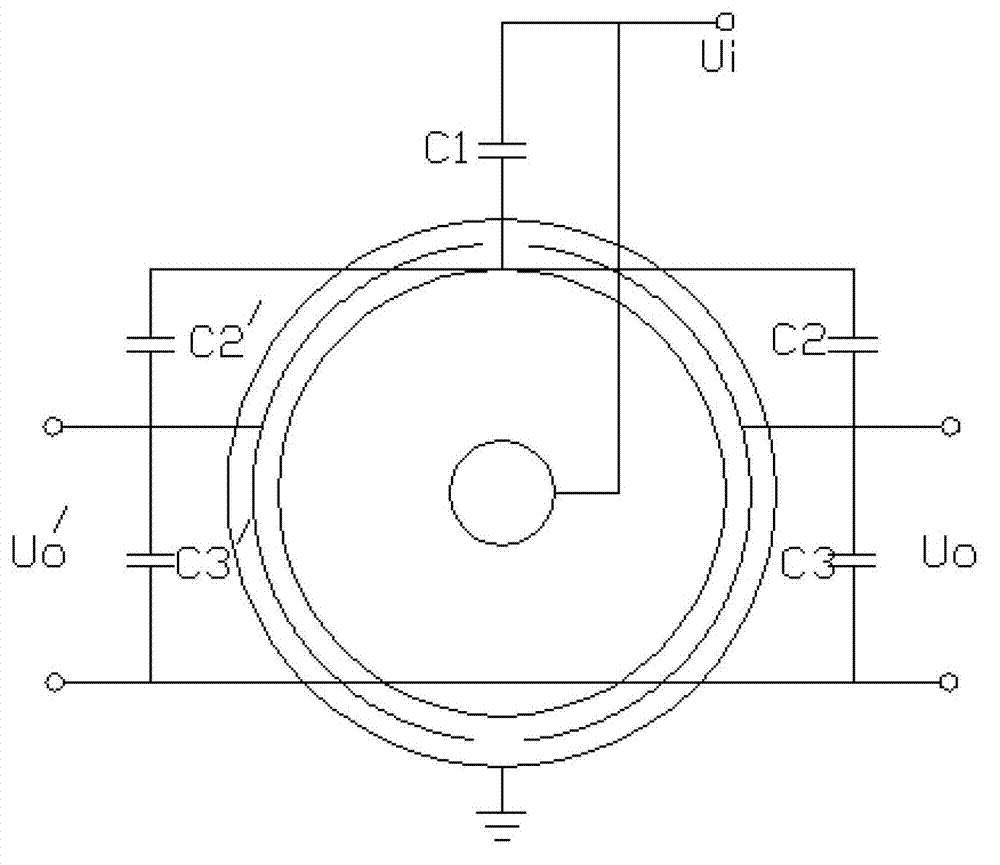
[0017] As shown in Figure 1, for the single-phase electronic current-voltage combination transformer for GIS, its structure is based on the traditional SF6 gas-insulated GIS current-voltage combination transformer structure, the outside is the pressure vessel shell 4, and the Rogowski coil 10 is fixed on the coil Inside the housing 9 , the Rogowski coil housing 9 is fixed in the pressure vessel housing 4 . The primary conductor 3 and the through-heart Rogowski coil form the current sensing head, and lead the signal collected by the current sensing head to the acquisition unit. The primary conductor 3 passes through the floating potential cylinder 7, and the insulation between the floating potential cylinder 7 and the pressure vessel shell 4 is required. Corresponding to the coaxial capacitor coaxially pierced on the primary conductor, its high-voltage capaci...


PUM


Abstract

The invention relates to an electronic-type current-voltage-combined transformer for a GIS (gas insulated switchgear). The electronic-type current-voltage-combined transformer comprises an external voltage container shell and a suspension potential barrel. A first conductor penetrates through the suspension potential barrel. A Rogowski coil current transformer and a coaxial capacitive voltage divider are mounted on the suspension potential barrel. The coaxial capacitive voltage divider comprises a high-voltage capacitor and at least two low-voltage capacitors. Each low-voltage capacitor forms an output channel. The low-voltage capacitor can be increased to multiple numbers such as two, functions of double-voltage instrument transformer sensing heads, double output and double protection can be achieved, and the electronic-type current-voltage-combined transformer has the advantages of small size, high interference resistance, high precision, high reliability, low cost and the like.

Description

technical field [0001] The invention relates to an electronic current-voltage combined transformer for GIS. Background technique [0002] At present, most electronic voltage transformers adopt capacitive voltage dividing structures, such as the structures disclosed in patent documents such as CN202384167U and CN202384166U. Use the coaxial structure of the primary shielding cover and the suspension cylinder as the high-voltage capacitor, and use the coaxial metal layer structure of the insulating medium as the low-voltage capacitor. The low-voltage capacitor side is connected to the upper resistor and introduced into the collector. After integration, amplification, and double A / D conversion , which is converted into an optical signal through a photoelectric conversion device, and then sent to the measurement and protection equipment after being synchronously processed by the fiber access merging unit. [0003] With the development of the power system towards large capacity, ...

Claims


Application Information

Patent Timeline
IPC IPC(8): H01F38/34G01R15/06H01G4/00
CPCH02B13/0356
Inventor 池立江田志国刘伟袁亮史文强魏少鹏冉允喜
Owner XUJI GRP
Why Eureka
Try Eureka