Optical lens and imaging equipment

An optical lens and imaging surface technology, applied in optics, optical components, instruments, etc., can solve the problem that the imaging quality of the lens is greatly affected, and achieve the effect of improving the camera experience, realizing the balance of high pixels, and realizing miniaturization

Active Publication Date: 2021-01-29
合肥联创光学有限公司
View PDF3 Cites 0 Cited by
  • Summary
  • Abstract
  • Description
  • Claims
  • Application Information

AI Technical Summary

Problems solved by technology

[0003] However, the reduction in lens size has a great impact on the imaging quality of the lens, especially for wide-angle lenses with large fields of view

Method used


Image

  • Optical lens and imaging equipment
  • Optical lens and imaging equipment
  • Optical lens and imaging equipment

Examples


no. 1 example

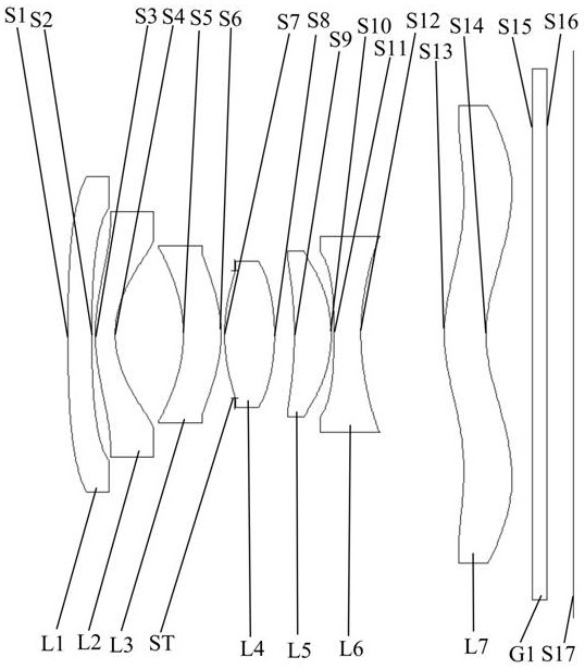
[0080] In the first embodiment of the present invention, the vertical distance between the inflection point of the object side S13 of the seventh lens and the optical axis is 1.935 mm, and the sagittal height relative to the center of the object side S13 of the seventh lens is 0.289 mm. The vertical distance between the inflection point of the image side S14 and the optical axis is 2.035 mm, and the sagittal height relative to the center of the image side S14 of the seventh lens is 0.371 mm.

[0081] Please refer to Table 1, the relevant parameters of each lens in the optical lens provided by the first embodiment of the present invention are shown in Table 1.

[0082] Table 1

[0083]

[0084] The surface coefficients of each aspheric surface of the optical lens provided by the first embodiment of the present invention are shown in Table 2.

[0085] Table 2

[0086]

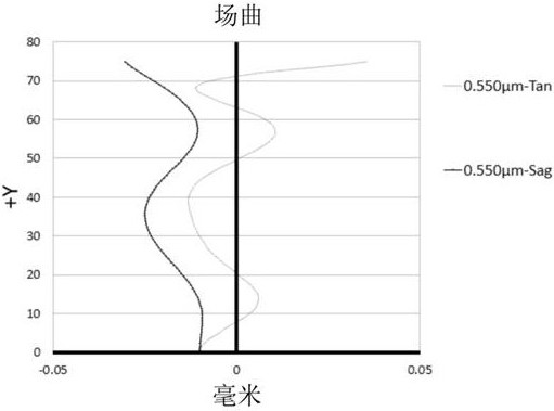
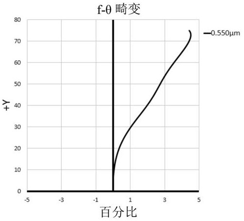
[0087] see figure 2 , image 3 , Figure 4 and Figure 5 , respectively show the field curvature ...

no. 2 example

[0093] The structure of the optical lens provided by the second embodiment of the present invention is substantially the same as that of the optical lens provided by the first embodiment, except that the curvature and material selection of each lens are different.

[0094] In the second embodiment of the present invention, the vertical distance between the inflection point of the object side S13 of the seventh lens and the optical axis is 1.835 mm, and the sagittal height relative to the center of the object side S13 of the seventh lens is 0.251 mm. The vertical distance between the inflection point of the image side S14 and the optical axis is 1.955 mm, and the sagittal height relative to the center of the image side S14 of the seventh lens is 0.336 mm.

[0095] Please refer to Table 3, the relevant parameters of each lens in the optical lens provided by the second embodiment of the present invention are shown in Table 3.

[0096] table 3

[0097]

[0098] The surface coe...

no. 3 example

[0107] The structure of the optical lens provided by the third embodiment of the present invention is substantially the same as that of the optical lens provided by the first embodiment, except that the curvature and material selection of each lens are different.

[0108] In the third embodiment of the present invention, the vertical distance between the inflection point of the object side S13 of the seventh lens and the optical axis is 1.795 mm, and the sagittal height relative to the center of the object side S13 of the seventh lens is 0.217 mm. The vertical distance between the inflection point of the image side S14 and the optical axis is 1.912 mm, and the sagittal height relative to the center of the image side S14 of the seventh lens is 0.298 mm.

[0109] Please refer to Table 5, the relevant parameters of each lens in the optical lens provided by the third embodiment of the present invention are shown in Table 5.

[0110] table 5

[0111]

[0112] The surface coeffi...


PUM


Abstract

The invention discloses an optical lens and an imaging device. The optical lens comprises in sequence from the object side to the imaging surface along the optical axis: a first lens with negative refractive power, the object side is convex and the image side is concave; The second lens with refractive power has a convex surface on its object side and concave surface on its image side; the third lens with positive refractive power has a concave surface on its object side and convex surface on its image side; the fourth lens with positive refractive power has its object Both the side and the image side are convex; the fifth lens with positive power has a concave surface on the object side and the convex surface on the image side; the sixth lens with negative power has concave surfaces on both the object side and the image side; The seventh lens with refractive power has a convex surface on the object side at the near optical axis, and a concave surface on the image side at the near optical axis, and both the object side and the image side of the seventh lens have at least one inflection point. The optical lens achieves a reasonable balance of large wide-angle, miniaturization and high pixels, and can effectively improve the user's camera experience.

Description

technical field [0001] The invention relates to the technical field of lens imaging, in particular to an optical lens and an imaging device. Background technique [0002] In recent years, camera lenses have been widely used in various fields, especially wide-angle lenses including ultra-wide-angle lenses and fisheye lenses play an important role in more and more occasions. In terms of photography, the wide-angle lens has the characteristics of short focus and large field of view, which can produce large barrel distortion to create special effects and bring strong visual impact to the observer. In terms of measurement, the wide-angle lens utilizes the characteristics of a large field of view to obtain more data in a single imaging to capture more scene information. At the same time, the market is increasingly demanding the miniaturization of lenses. [0003] However, the reduction in lens size has a great impact on the imaging quality of the lens, especially for wide-angle ...

Claims


Application Information

Patent Timeline
Patent Type & Authority Patents(China)
IPC IPC(8): G02B13/00G02B13/06G02B13/18
CPCG02B13/0045G02B13/06G02B13/18
Inventor 于笑枝曾昊杰刘绪明曾吉勇
Owner 合肥联创光学有限公司
Why Eureka
Try Eureka