Device for measuring disruptions in a controlled magnetic field

A technology of measuring equipment and equipment, applied in the direction of measuring devices, electric/magnetic exploration, geophysical surveying, etc.

Pending Publication Date: 2020-12-04
ONTECH SECURITY SL
View PDF24 Cites 0 Cited by
  • Summary
  • Abstract
  • Description
  • Claims
  • Application Information

AI Technical Summary

Problems solved by technology

At the same time, this presents a

Method used


Image

  • Device for measuring disruptions in a controlled magnetic field
  • Device for measuring disruptions in a controlled magnetic field
  • Device for measuring disruptions in a controlled magnetic field

Examples


Embodiment Construction

[0041] Various aspects of the invention include a controlled magnetic field sensor capable of detecting discontinuities in the magnetic field around a single conductor or antenna having the ability to emit a controlled magnetic field and at the same time to detect said field The specificity of any discontinuity in , such that by means of the representation of the discontinuity the object generating the discontinuity can be detected and distinguished.

[0042] In this specification, the terms "circuitry" and "circuitry" refer to electronic physical components—that is, hardware components—as well as any software and / or firmware that can configure or be liable to configure the hardware and / or be associated with the hardware in any way - machine code. In some parts of the description, hardware and software may be abbreviated as HW and SW, respectively.

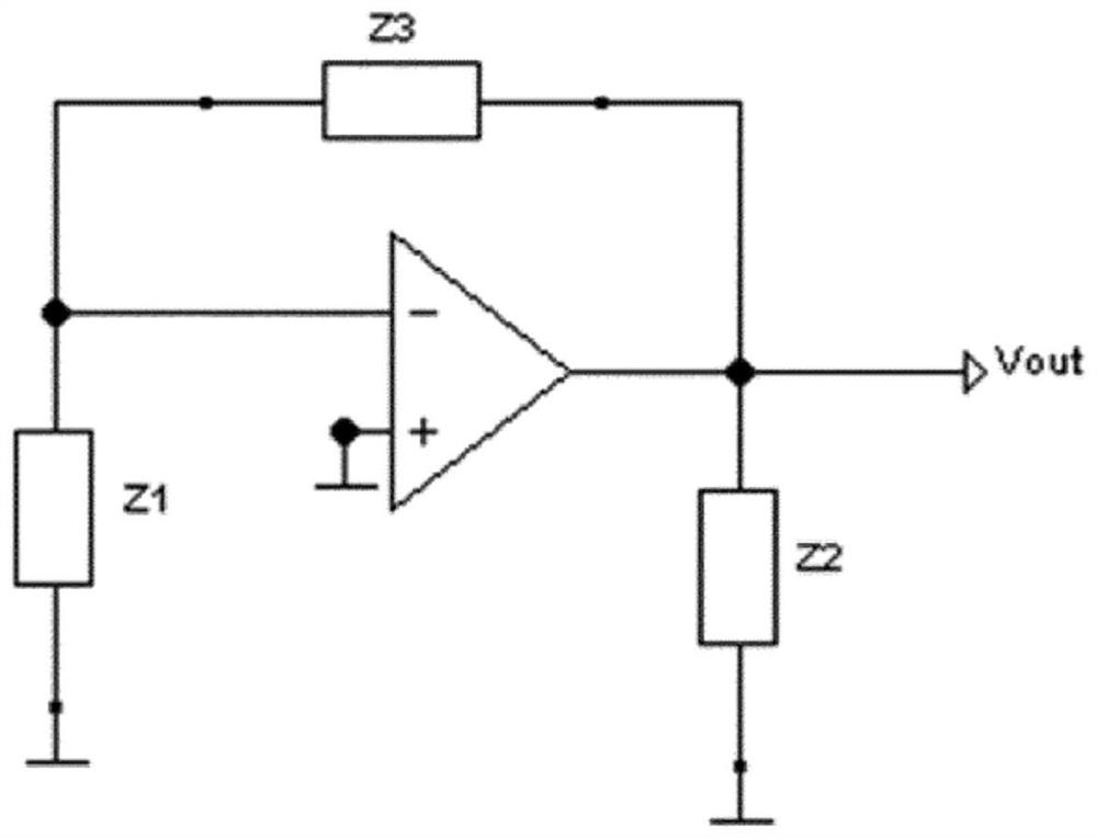
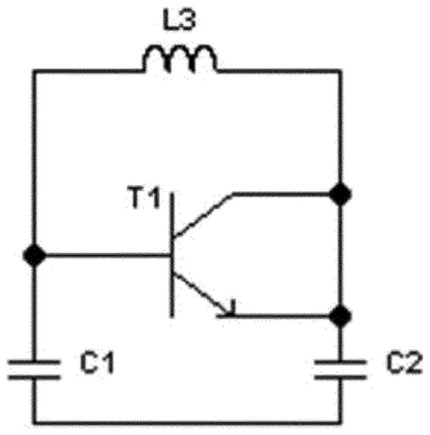
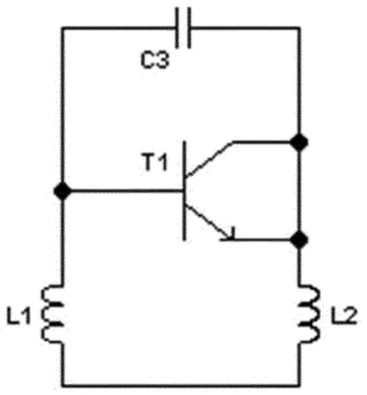
[0043] Referring to the drawings, there is shown a sensor CMF 100, which is a hybrid analog-digital sensor, comprising an oscil...


PUM


Abstract

A device for measuring disruptions in a controlled magnetic field and generated by the device itself surrounding a sole conductive element, antenna or electrode (101) and comprising, at least: a controlled magnetic field sensor (100) comprising, in turn, an oscillator circuit (102) connected to at least one electrode (101), a digital module (103); and a processor (105) connected to the digital module (103). The applications of the device that is the object of the invention are all those requiring the detection of an object prior to it resulting in the violation of the restricted space. Amongstthese applications we can highlight the following: the localisation of people, industrial security applications, robotics, domestic security applications, military applications and vehicle security applications.

Description

technical field [0001] The invention relates to a device comprising a controlled magnetic field (CMF) sensor physically integrated in an ASIC (Application Specific Integrated Circuit). Another object of the invention is a method of measuring electromagnetic fields around conductors and the multiple uses of the sensor in different technical applications, such as localization of persons, domestic and industrial security applications, robotics, military applications and for Safety applications for the transport of goods and people, work-related and domestic protection and safety applications, and applications in the logistics sector. Background technique [0002] When charges move on a conductor, the charges create an EM (EM, electromagnetic) field around the conductor. Oscillations of the source charge generate waves that radiate energy from the conductor, and the EM field is the means by which the energy can be delivered remotely from its emitter. [0003] Electromagnetic w...

Claims


Application Information

Patent Timeline
IPC IPC(8): G01D21/00H03K17/95H03K17/955
CPCG01D21/00H03K17/9532H03K17/955H03K2217/960765G08B13/2491G01V3/08G08B13/24G01R33/02G01R33/093G01R33/028G01V3/081G01V3/15
Inventor 胡安·阿蓬特·路易斯
Owner ONTECH SECURITY SL
Why Eureka
Try Eureka