Eye massager
An eye and connecting rod technology, applied in the field of eye massager, can solve problems such as unsatisfactory massage comfort, inability to massage temples and forehead parts, etc., and achieve the effect of relieving eye fatigue, suitable massage intensity and improving experience effect.
- Summary
- Abstract
- Description
- Claims
- Application Information
AI Technical Summary
Problems solved by technology
Method used
Image
Examples
Embodiment 1
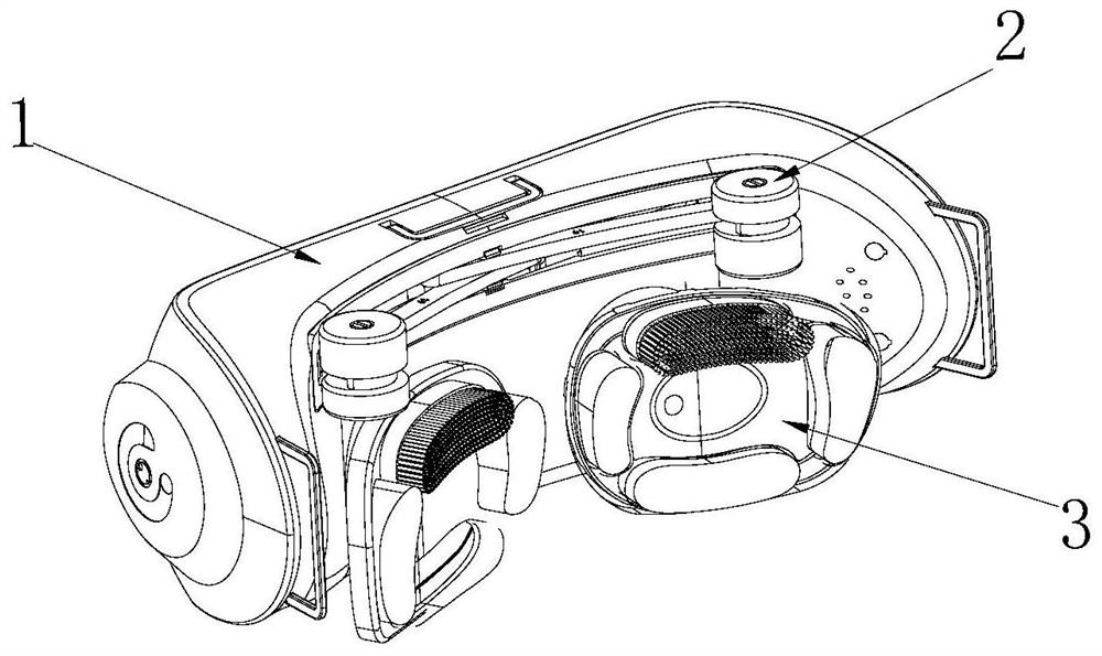
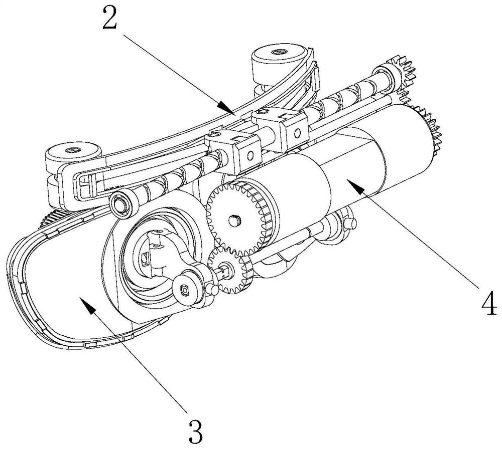
[0050] Such as Figure 1-2 As shown, the present application provides an eye massager, including an outer shell 1, a driving mechanism 4, a first massage mechanism 2 for massaging the temples and forehead, and a second massage mechanism 3 for massaging the eyes , the driving mechanism 4 is fixed in the outer casing 1, and the first massage mechanism 2 and the second massage mechanism 3 are connected to the driving mechanism 4.
[0051] Combining with the description of the above structure, it can be seen that the first massage mechanism 2 and the second massage mechanism 3 are driven by the driving mechanism 4 to massage the temples and eye points of the eye socket respectively. Compared with the traditional eye massager, the eye massager The first massage mechanism 2 for the temple and forehead is added. While massaging the acupuncture points around the eyes, it can also press and massage the temple and forehead. The massage strength is appropriate and can effectively relieve...
Embodiment 2
[0071] Please refer to Figure 13 The difference between this embodiment and Embodiment 1 is that the drive mechanism 4 used to drive the first massage mechanism 2 and the second massage mechanism 3 to move is different. In this embodiment, the drive mechanism 4 includes a first drive motor 47 and a first drive motor 47. The second drive motor 48 , the first drive motor 47 and the second drive motor 48 are engaged with the first massage mechanism 2 and the second massage mechanism 3 respectively.
[0072] Specifically, the driving mechanism 4 also includes a first speed change gear 44, a second speed change gear 45 and a third speed change gear 46, and the first speed change gear 44 and the third speed change gear 46 are connected to the first massage mechanism 2 and the second massage mechanism 3 respectively. Connect, the output ends of the first driving motor 47 and the second driving motor 48 are provided with the first transmission gear 42 and the second transmission gear...
Embodiment 3
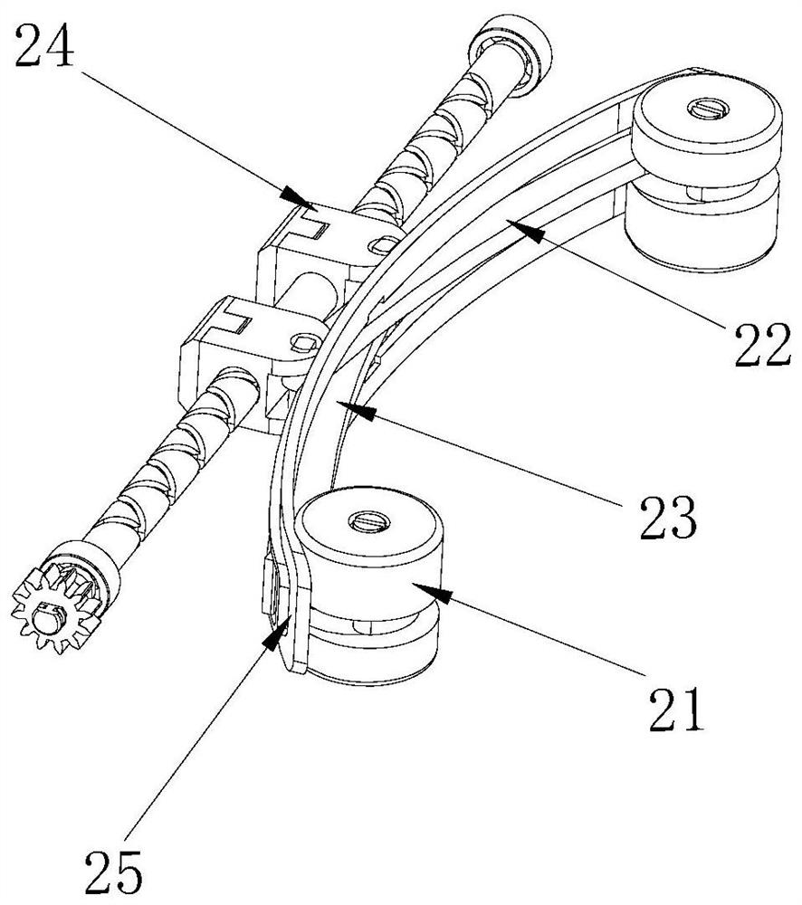
[0075] Please refer to Figure 14-17 , the difference between this embodiment and Embodiment 2 is that the structure of the first transmission assembly 24 used is different. In this embodiment, the first transmission assembly 24 also includes an electronic limit switch plate 247, and the screw rod is a sliding screw rod 244, the electronic limit switch plate 247 is fixed on the sliding screw rod 244 between the first connecting unit 242 and the second connecting unit 243, and the first connecting unit 242 and the second connecting unit 243 are respectively slidably arranged on the sliding screw rod 244 Above, the first connecting rod 22 and the second connecting rod 23 are respectively correspondingly connected with the first connecting unit 242 and the second connecting unit 243; in this embodiment, the first connecting unit 242 and the second connecting unit 243 are directly sliding The third slide block 245 and the fourth slide block 246 that are located on the slide screw ...
PUM
 Abstract
Description
Claims
Application Information
 - R&D
- Intellectual Property
- Life Sciences
- Materials
- Tech Scout
- Unparalleled Data Quality
- Higher Quality Content
- 60% Fewer Hallucinations
Browse by: Latest US Patents, China's latest patents, Technical Efficacy Thesaurus, Application Domain, Technology Topic, Popular Technical Reports.
© 2025 PatSnap. All rights reserved.Legal|Privacy policy|Modern Slavery Act Transparency Statement|Sitemap|About US| Contact US: help@patsnap.com


