Automatic thin plate bending equipment for industrial production

An automatic and equipment technology, applied in the direction of metal processing equipment, manufacturing tools, feeding devices, etc., can solve the problems of cutting off unnecessary thin plates and automatic bending of thin plates

Inactive Publication Date: 2020-12-08
孟飞星
View PDF1 Cites 3 Cited by
  • Summary
  • Abstract
  • Description
  • Claims
  • Application Information

AI Technical Summary

Problems solved by technology

[0005] In order to overcome the shortcomings of the existing thin plate bending device, which cannot automatically bend thin plates and cut off redundant thin plates, the technical problem to be solved is to provide a device that can automatically bend thin plates and can automatically Automatic thin plate bending equipment for industrial production that cuts off excess thin plates

Method used


Image

  • Automatic thin plate bending equipment for industrial production
  • Automatic thin plate bending equipment for industrial production
  • Automatic thin plate bending equipment for industrial production

Examples


Embodiment 1

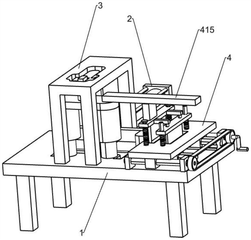
[0029] An automatic thin plate bending equipment for industrial production, such as figure 1 As shown, it includes a workbench 1, a bending mechanism 2 and a pressing mechanism 3. A bending mechanism 2 is installed on the workbench 1. A pressing mechanism 3 is arranged on the workbench 1 outside the bending mechanism 2. The pressing mechanism 3 cooperates with bending mechanism 2.

[0030] When it is necessary to bend the thin plate, the user places the thin plate on the workbench 1 on the lower side of the pressing mechanism 3, and then the user moves the thin plate to the left to a suitable position, and then the user cuts off the thin plate with a suitable length by a cutting machine, and the user passes the bending When the bending mechanism 2 bends the thin plate, the bending mechanism 2 works to make the pressing mechanism 3 work to fix and limit the thin plate, and the user resets the bending mechanism 2, so that the pressing mechanism 3 can be reset to release the fixi...

Embodiment 2

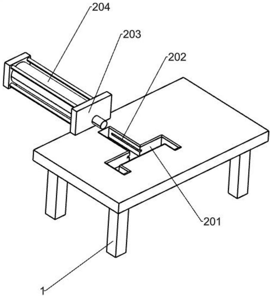
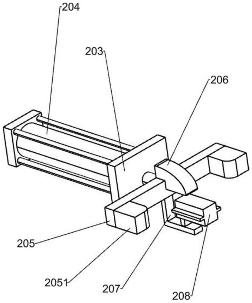
[0032] On the basis of Example 1, as figure 1 , figure 2 , image 3 As shown, the bending mechanism 2 includes a mounting plate 203, a cylinder 204, a push plate 205, a bending block 2051, a bump 206, an L-shaped plate 207 and a slider 208, and the top left side of the workbench 1 has a sliding groove 201 , the workbench 1 on both sides of the slide groove 201 is provided with a linear slide groove 202, and the workbench 1 on the rear side of the slide groove 201 is provided with a mounting plate 203, and a cylinder 204 is installed on the mounting plate 203 through bolts, and the expansion and contraction of the cylinder 204 The rod passes through the mounting plate 203, and the front end of the telescopic rod of the cylinder 204 is fixedly connected with a push plate 205, and two bending blocks 2051 are fixed on the front side wall of the push plate 205, and a projection 206 is embedded in the middle of the top of the push plate 205. An L-shaped plate 207 is fixedly conne...

Embodiment 3

[0037] On the basis of Example 2, such as figure 1 , Figure 7 , Figure 8 and Figure 10 As shown, it also includes a fine-tuning cutting mechanism 4, and the fine-tuning cutting mechanism 4 includes a fixed support 401, a leading screw 402, a connecting nut 403, a connecting plate 404, a guide rail 405, a guide block 406, a pulley 407, a belt 408, a rocker 409, sliding bar 410, sliding plate 411, return spring 412, cutting knife 413, contact plate 414 and lower pressing plate 415, four fixed supports 401 are fixedly connected on the right side workbench 1 of the mounting frame 301, and the left and right two are adjacent A lead screw 402 is installed between the fixed supports 401, and a connecting nut 403 is provided on the lead screw 402 through threaded connection, and a connecting plate 404 is fixed between the tops of the front and rear connecting nuts 403, and the top left of the connecting plate 404 There is a sliding hole 4041 on the side. Two guide rails 405 are ...


PUM


Abstract

The invention relates to bending equipment for industrial production, in particular to automatic thin plate bending equipment for industrial production. According to the technical scheme, the automatic thin plate bending equipment for the industrial production comprises a workbench and a pressing mechanism, and a bending mechanism is installed on the workbench; and the pressing mechanism is arranged on the side, close to the bending mechanism, of the workbench, and the pressing mechanism is matched with the bending mechanism. According to the automatic thin plate bending equipment for the industrial production, thin plates needing to be bent can be fixed and limited through the pressing mechanism, the thin plates can be bent through the bending mechanism, so that automatic bending of the thin plates is achieved; and the redundant thin plates can be cut off through a fine adjustment cutting mechanism, so that the thin plates with different lengths are bent conveniently.

Description

technical field [0001] The invention relates to a bending equipment for industrial production, in particular to an automatic thin plate bending equipment for industrial production. Background technique [0002] The industrial production index is the physical volume index of industrial products compiled with the weighted arithmetic mean. It is an index commonly used in western countries to calculate and reflect the speed of industrial development, and it is also the preferred index for economic analysis. The industrial production index is a relative index that measures manufacturing, The real output of mining and public utilities is measured based on quantity, not amount; the index reflects the prosperity and development trend of the industrial economy in a certain period; like other relative indicators, when using the industrial production index, it must Pay attention to the comparability of data, which must be used in combination with absolute indicators to explain the prob...

Claims


Application Information

Patent Timeline
Patent Type & Authority Applications(China)
IPC IPC(8): B21D5/04B21D43/28B21D43/00
CPCB21D5/045B21D43/003B21D43/287
Inventor 孟飞星
Owner 孟飞星
Why Eureka
Try Eureka