Anti-abrasion batching machine for building

An anti-wear and batching machine technology, which is applied in batching storage, sales raw material supply devices, clay preparation devices, etc., can solve the problems of wear, large contact friction area between the conveyor belt and the lower end of the storage port, and material leakage, so as to avoid contact The effect of excessive friction

Inactive Publication Date: 2020-12-08
新沂沭东建设工程有限公司
View PDF0 Cites 0 Cited by
  • Summary
  • Abstract
  • Description
  • Claims
  • Application Information

AI Technical Summary

Problems solved by technology

[0002] Concrete batching machine, also known as batching machine and automatic sand and gravel batching machine, is an automatic equipment for the quantitative distribution of various materials such as sand and gravel. It is mainly used in the concrete construction industry to replace manual scales or volumetric measurement. The upper part is the raw material storage hopper, the lower part is the weighing hopper, and the bottom is the unloading conveyor belt. The storage hopper is used to store the raw materials to be mixed. The bottom of the storage hopper is directly facing the batching conveyor belt. The belt stops when the machine starts to take out the raw materials in the storage hopper to the set value. Therefore, this type of design structure is simple and cheap, so it is the most widely used. However, this type of structure usually attaches the conveyor belt to the outlet at the lower end of the storage hopper, and rotates on the conveyor belt. When discharging, the contact friction area between the conveyor belt and the lower end of the storage port is relatively large, so that after long-term use of the conveyor belt, serious wear occurs, and there is an improvement, and with this design, the sand and gravel in the storage hopper can easily pass through the conveyor belt and the storage hopper There is a gap between the gaps, there is material leakage, and there is an improvement

Method used


Image

  • Anti-abrasion batching machine for building
  • Anti-abrasion batching machine for building

Examples


Embodiment Construction

[0014] The following will clearly and completely describe the technical solutions in the embodiments of the present invention with reference to the accompanying drawings in the embodiments of the present invention. Obviously, the described embodiments are only some, not all, embodiments of the present invention. Based on the embodiments of the present invention, all other embodiments obtained by persons of ordinary skill in the art without making creative efforts belong to the protection scope of the present invention.

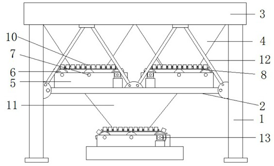
[0015] see Figure 1-2 , the present invention provides a technical solution: an anti-wear batching machine for construction, comprising a protective frame 1, the top of the protective frame 1 is fixedly connected with a top frame 3, and the lower end of the top frame 3 is located inside the protective frame 1 and is fixedly connected with a The two ends of the connecting frame 2 and the top frame 3 are respectively fixedly connected with a storage hopper 4, a...


PUM


Abstract

The invention discloses an anti-abrasion batching machine for building. The anti-abrasion batching machine comprises a protective frame, a top frame is fixedly connected to the top of the protective frame, a connecting frame is fixedly connected to the lower end of the top frame and located in the protective frame, storage bins are fixedly connected to the two ends of the inner part of the top frame correspondingly, and outlets are formed in the lower ends of the storage bins; Through the design that a plurality of dividing strips are evenly and equidistantly arranged at the upper ends of conveying belts and the design that the upper ends of the dividing strips are attached to the outlets in the lower ends of the storage bins, and certain gaps are formed between the conveying belts and thestorage bins, so that the situation that the conveying belts are damaged due to too large contact friction force between the conveying belts and the storage bins is avoided; and through the design ofside plates at the front ends and the rear ends of the conveying belts, the side plates act and are effectively attached to the two sides of the outer portions of the bottoms of the storage bins, andtherefore the situation that materials leak through the gaps between the conveying belts and the storage bins is avoided, and simpleness and convenience are achieved.

Description

technical field [0001] The invention relates to the technical field of batching machines, in particular to an anti-wear batching machine for construction. Background technique [0002] Concrete batching machine, also known as batching machine and automatic sand and gravel batching machine, is an automatic equipment for the quantitative distribution of various materials such as sand and gravel. It is mainly used in the concrete construction industry to replace manual scales or volumetric measurement. The upper part is the raw material storage hopper, the lower part is the weighing hopper, and the bottom is the unloading conveyor belt. The storage hopper is used to store the raw materials to be mixed. The bottom of the storage hopper is directly facing the batching conveyor belt. The belt stops when the machine starts to take out the raw materials in the storage hopper to the set value. Therefore, this type of design structure is simple and cheap, so it is the most widely used...

Claims


Application Information

Patent Timeline
Patent Type & Authority Applications(China)
IPC IPC(8): B28C7/06B28C7/00
CPCB28C7/0076B28C7/067
Inventor 不公告发明人
Owner 新沂沭东建设工程有限公司
Why Eureka
Try Eureka