
Gas turbine rotor and gas turbine

A technology for gas turbines and rotors, used in machines/engines, mechanical equipment, engine components, etc., to solve the problem that the root of the blade cannot fit with the surface of the tongue and groove.

Pending Publication Date: 2020-12-08
AECC COMML AIRCRAFT ENGINE CO LTD
View PDF6 Cites 0 Cited by
  • Summary
  • Abstract
  • Description
  • Claims
  • Application Information

AI Technical Summary

Problems solved by technology

[0007] The purpose of the present invention is to provide a gas turbine rotor and a gas turbine to improve the problem in the prior art that the root of the blade cannot fit the surface of the tongue and groove when assembling the blade and the disc

Method used


Image

  • Gas turbine rotor and gas turbine
  • Gas turbine rotor and gas turbine
  • Gas turbine rotor and gas turbine

Examples


Embodiment Construction

[0029] The following will clearly and completely describe the technical solutions in the embodiments of the present invention with reference to the accompanying drawings in the embodiments of the present invention. Obviously, the described embodiments are only some, not all, embodiments of the present invention. The following description of at least one exemplary embodiment is merely illustrative in nature and in no way taken as limiting the invention, its application or uses. Based on the embodiments of the present invention, all other embodiments obtained by persons of ordinary skill in the art without creative efforts fall within the protection scope of the present invention.

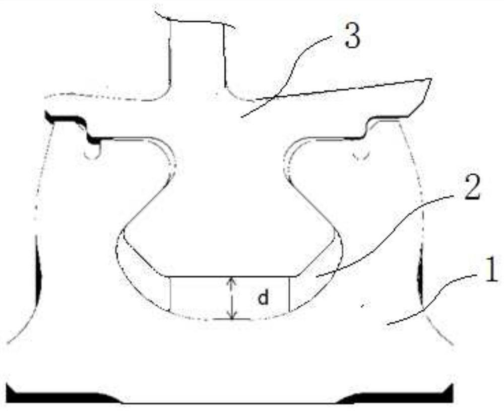
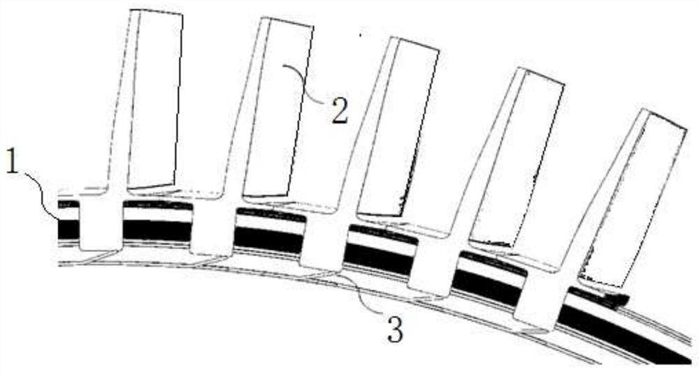
[0030] figure 2 A structural schematic diagram of a cross section of the gas turbine rotor of this embodiment is shown. like figure 2 As shown, the gas turbine rotor in this embodiment includes a disk 1 and a plurality of blades 2 arranged along the circumference of the disk 1 .

[0031] The per...


PUM


Abstract

The invention relates to a gas turbine rotor and a gas turbine. The gas turbine rotor comprises a wheel disc (1), a mortise, blades (2) and elastic pushing and pressing parts (3), wherein the mortisecomprises an opening located in the circumferential face of the wheel disc and an inner cavity located on the inner side of the opening, and the width of the opening is smaller than that of the innercavity; each blade (2) comprises a connecting part located at the root of the blade, and each connecting part comprises a first part matched with the inner cavity of the mortise and a second part matched with the opening of the mortise; and the elastic pushing and pressing parts (3) are arranged at the bottom of the mortise and used for pushing and pressing the blades (2) towards the direction away from the center of the wheel disc (1) along the radial direction of the wheel disc (1). According to the technical scheme, the elastic pushing and pressing parts are arranged at the bottom of the mortise and used for pushing and pressing the blades towards the direction away from the wheel disc along the radial direction of the wheel disc, and therefore, the problem that in the related art, whenthe blades and the wheel disc are assembled, the roots of the blades cannot attach to the surface of the mortise is solved.

Description

technical field [0001] The invention relates to the field of aeroengines, in particular to a gas turbine rotor and a gas turbine. Background technique [0002] figure 1 A structural schematic view of a longitudinal section of a related art gas turbine rotor passing through its axis is shown. like figure 1 As shown, the gas turbine rotor in the related art includes a disk 1 and a plurality of blades 3 arranged along the circumference of the disk 1. A tenon and groove 2 extending along the circumference of the disk 1 is provided on the peripheral surface of the disk 1. The groove 2 includes an opening on the peripheral surface of the wheel disc 1 and an inner cavity positioned on the inner side of the opening, the width of the opening of the tongue and groove 2 is smaller than the width of the inner cavity, and the root of the blade 3 is provided with a The matching connecting part, the connecting part includes a first part that fits the inner cavity of the tongue and groov...

Claims


Application Information

Patent Timeline
Patent Type & Authority Applications(China)
IPC IPC(8): F01D5/02F01D5/10F01D5/30
CPCF01D5/027F01D5/10F01D5/3007
Inventor 胡淑慧刘洋钟姝
Owner AECC COMML AIRCRAFT ENGINE CO LTD
Learn More