Method and system for locating equipment fault sound source

A technology for sound source localization and equipment failure. It is applied in localization, neural learning methods, radio wave measurement systems, etc. It can solve problems such as being susceptible to interference, low positioning accuracy, and poor real-time performance, avoiding iterative calculations and suppressing environmental noise. Interfere, reduce the effect of real-time requirements

Active Publication Date: 2021-06-15
SHANDONG UNIV
View PDF0 Cites 0 Cited by
  • Summary
  • Abstract
  • Description
  • Claims
  • Application Information

AI Technical Summary

Problems solved by technology

[0006] In summary, the current sound source localization methods generally have the problems of low positioning accuracy, poor real-time performance, and easy to be interfered.

Method used


Image

  • Method and system for locating equipment fault sound source
  • Method and system for locating equipment fault sound source
  • Method and system for locating equipment fault sound source

Examples


Embodiment 1

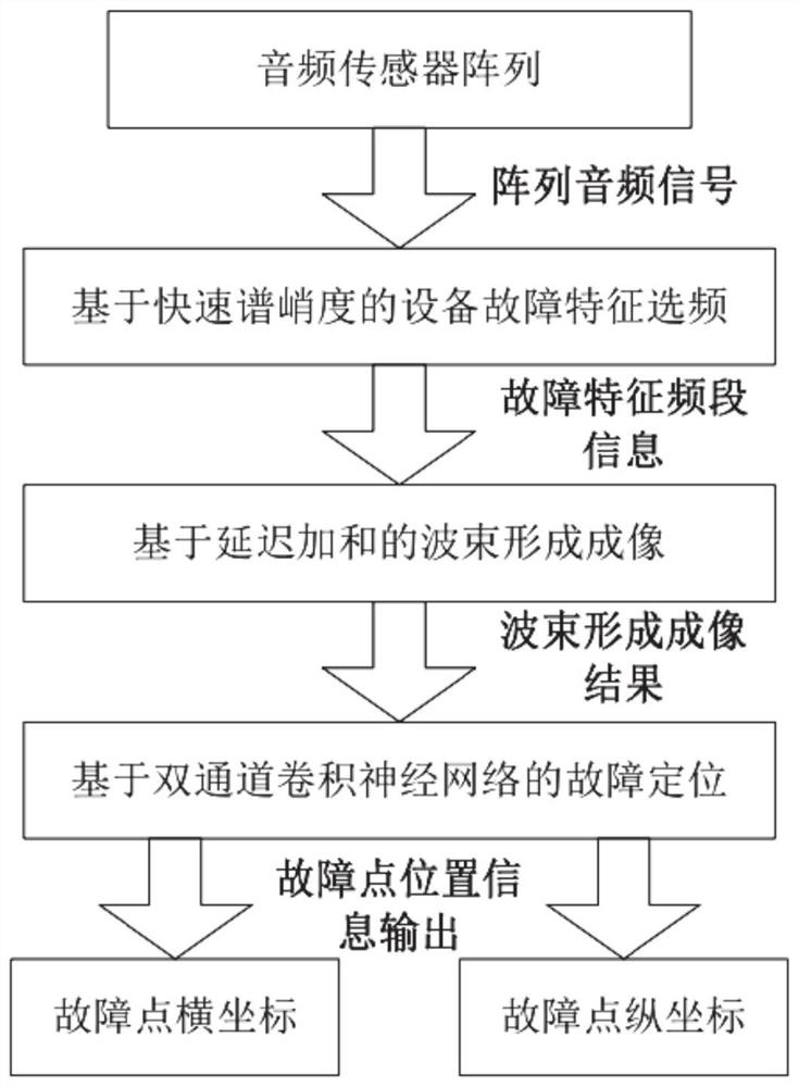
[0043] A sound source localization method for equipment faults based on fast spectral kurtosis beamforming and dual-channel convolutional neural network, such as figure 1 shown, including the following steps:

[0044] Step 1. Collect the audio signal of the device through the audio sensor array.

[0045]Through the audio sensor array, the audio signal during the operation of the equipment is collected. In order to facilitate the calculation of subsequent positioning results, the audio sensor array is usually arranged in a rectangular or square structure. During the training process, this signal is the sensor array audio signal of known multiple sound source positions. When actually locating the fault point of the equipment, this signal is the audio signal of the equipment collected by the sensor.

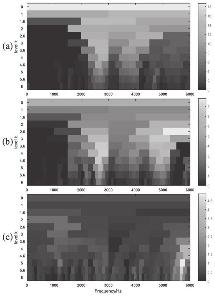
[0046] Step 2. Fault characteristic frequency selection based on fast spectral kurtosis algorithm.

[0047] The specific steps of fault feature frequency selection based on fast...

Embodiment 2

[0094] A device fault sound source localization system, comprising:

[0095] an audio sensor array configured to collect audio signals during operation of the device;

[0096] The fault feature frequency selection module is configured to take the collected equipment sound signal as the signal to be analyzed, perform Fourier transform on the signal to be analyzed, calculate the fast spectral kurtosis index of the signal to be analyzed according to the transformation result, and determine according to the fast spectral kurtosis index Fault feature frequency selection results;

[0097] The beamforming imaging module is configured to calculate a cross-spectrum matrix and a delay sum steering response according to the frequency selection result of the fault feature and the signal to be analyzed, and obtain the delay sum beamforming imaging result of the fault frequency selection;

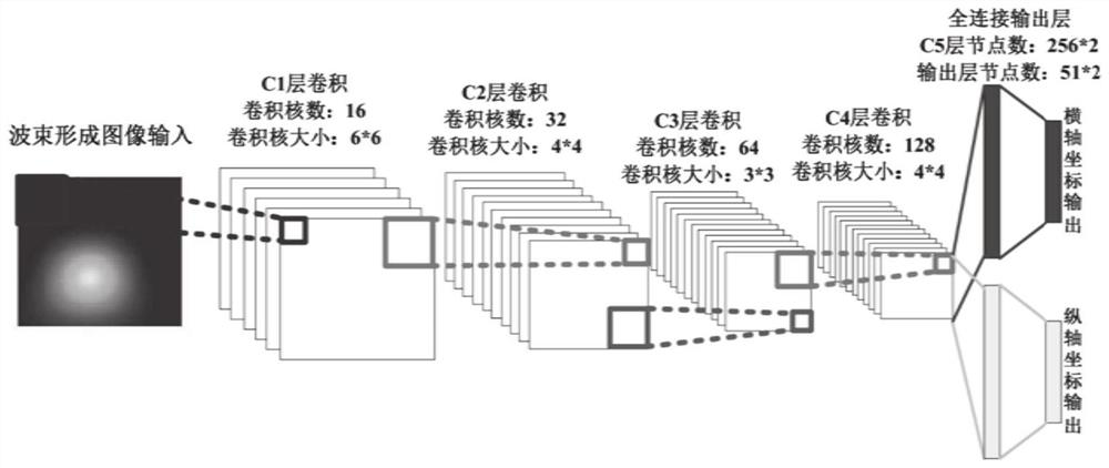
[0098] The sound source location module is configured to input the delay-sum beamforming imaging res...

Embodiment 3

[0100] A computer-readable storage medium, in which a plurality of instructions are stored, and the instructions are suitable for being loaded by a processor of a terminal device and executing the above-mentioned method for locating a sound source of a device failure.


PUM


Abstract

The present invention provides a method and system for locating the sound source of an equipment failure. The collected equipment sound signal is used as the signal to be analyzed, the signal to be analyzed is subjected to Fourier transform, and the fast spectral kurtosis index of the signal to be analyzed is calculated according to the transformation result. The fast spectrum kurtosis index determines the result of fault feature frequency selection; calculates the cross-spectrum matrix and the delay sum guide response according to the fault feature frequency selection result and the signal to be analyzed, and obtains the delay sum beamforming imaging result of fault frequency selection; the delay sum And the beamforming imaging results are input into the trained two-channel convolutional neural network to obtain the location information of the fault sound source. The invention has the advantages of good real-time performance, high positioning accuracy, strong generalization ability and the like.

Description

technical field [0001] The invention belongs to the technical field of equipment fault sound source localization, and specifically relates to a method and system for equipment fault sound source localization. Source location method and system. Background technique [0002] The statements in this section merely provide background information related to the present invention and do not necessarily constitute prior art. [0003] The vibration and sound signals generated during the operation of the equipment contain a wealth of equipment state information. The state of the equipment can be effectively reflected by collecting the vibration and sound signals and performing signal processing. For equipment maintenance in industrial production, it is not only necessary to provide equipment fault information, but also provide accurate fault location information, which is helpful for rapid troubleshooting of maintenance work. [0004] For scenarios where vibration signal collection ...

Claims


Application Information

Patent Timeline
Patent Type & Authority Patents(China)
IPC IPC(8): G01M13/045G01S5/18G06N3/04G06N3/08
CPCG01M13/045G01S5/18G06N3/08G06N3/045
Inventor 常发亮蒋沁宇刘春生赵子健
Owner SHANDONG UNIV
Why Eureka
Try Eureka