
Electrical discharge machine with time slice power supply system and method

A technology of time slices and waveforms, applied in power circuits, electric processing equipment, metal processing equipment, etc.

Active Publication Date: 2020-12-08
JOHNSON TECH CO LTD
View PDF10 Cites 0 Cited by
  • Summary
  • Abstract
  • Description
  • Claims
  • Application Information

AI Technical Summary

Problems solved by technology

The waveform can only be changed by changing the hardware configuration of the EDM system power supply

Method used


Image

  • Electrical discharge machine with time slice power supply system and method
  • Electrical discharge machine with time slice power supply system and method
  • Electrical discharge machine with time slice power supply system and method

Examples


Embodiment Construction

[0014] Before embodiments of the invention are explained, it is to be understood that the invention is not limited to details of operation or construction; and the arrangements of parts set forth in the following description or shown in the drawings. The invention is capable of various other embodiments and of being practiced or carried out in alternative ways not expressly disclosed herein.

[0015] Also, it is to be understood that the phraseology and terminology used herein are for the purpose of description and should not be regarded as limiting. The use of "comprises" and "comprises" and variations thereof encompasses the items listed thereafter and equivalents thereof, as well as additional items and equivalents thereof. Additionally, enumerations may be used in the description of various embodiments. Unless expressly stated otherwise, the use of enumeration should not be construed to limit the invention to any particular order or number of components. Neither is the u...


PUM


Abstract

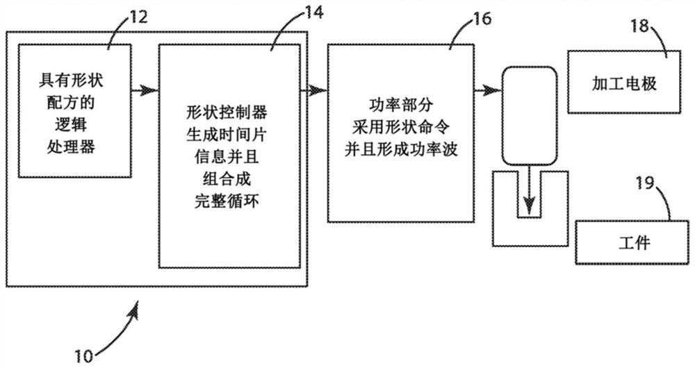
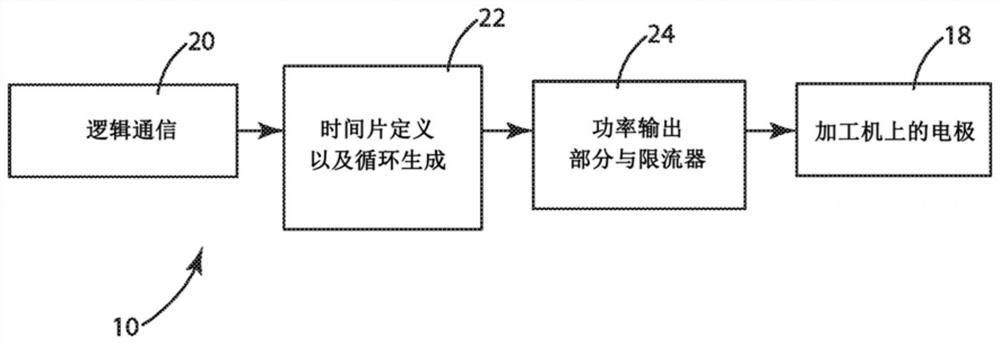
The specification discloses an electrical discharge machining (EDM) system and method capable of defining an unlimited number of waveforms. The system and method define logical waveforms using a plurality of time slices, each having a voltage and a width. The time slices are applied to the system power section where they are amplified and delivered to the electrode.

Description

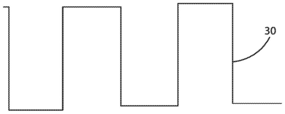
technical field [0001] The present invention relates to an electrical discharge machining (electrical discharge machining, EDM) system and method, in particular to a control system and power supply for the EDM system and method. Background technique [0002] Electrical discharge machining (EDM), also known as spark machining, spark erosion, combustion, die-cutting, wire combustion or wire erosion, is a manufacturing process that uses electrical discharges to achieve a desired shape. Material is removed from the workpiece by a series of rapidly cycling electrical sparks between two electrodes. One of the electrodes is the tool, or simply an electrode, and the other of the electrodes is the workpiece. [0003] EDM systems and methods, as well as control systems and power supplies for such systems and methods, are well known to those skilled in the art. Figure 3 shows a typical prior art standard waveform 30 used in a system for powering an electrode spark. It can be seen th...

Claims


Application Information

Patent Timeline
Patent Type & Authority Applications(China)
IPC IPC(8): B23H1/02B23H7/02B23H7/18B23H7/20
CPCB23H1/022B23H2300/20B23H1/024
Inventor 金·迈克尔·格罗滕休斯
Owner JOHNSON TECH CO LTD
Features
  • Generate Ideas
  • Intellectual Property
  • Life Sciences
  • Materials
  • Tech Scout
  • Unparalleled Data Quality
  • Higher Quality Content
  • 60% Fewer Hallucinations
Learn More