
Dust collector air path assembly and cleaning equipment

A technology for vacuum cleaners and components, which is applied in the direction of cleaning equipment, vacuum cleaners, suction filters, etc., and can solve the problems of uncompact structure of vacuum cleaners, and achieve the effects of reduced space occupation, high efficiency of air in and out, and short air inlet path

Pending Publication Date: 2020-12-11
BEIJING ROCKROBO TECH CO LTD
View PDF0 Cites 5 Cited by
  • Summary
  • Abstract
  • Description
  • Claims
  • Application Information

AI Technical Summary

Problems solved by technology

[0004] The purpose of the present invention is to provide a vacuum cleaner air path assembly and cleaning equipment to solve the problem of the vacuum cleaner structure is not compact

Method used


Image

  • Dust collector air path assembly and cleaning equipment
  • Dust collector air path assembly and cleaning equipment
  • Dust collector air path assembly and cleaning equipment

Examples


Embodiment Construction

[0042] In order to make the object, technical solution and advantages of the present invention clearer, the present invention will be further described in detail below in combination with specific embodiments and with reference to the accompanying drawings. It should be understood that these descriptions are exemplary only, and are not intended to limit the scope of the present invention. Also, in the following description, descriptions of well-known structures and techniques are omitted to avoid unnecessarily obscuring the concept of the present invention.

[0043] A schematic diagram of a layer structure according to an embodiment of the invention is shown in the drawing. The figures are not drawn to scale and certain details may have been omitted. The shapes of the various regions and layers shown in the figure, as well as their relative sizes and positional relationships are only exemplary, and may deviate due to manufacturing tolerances or technical limitations in practi...


PUM


Abstract

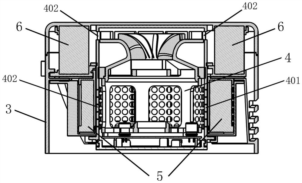
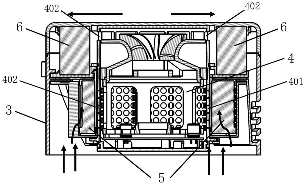
The invention provides a dust collector air path assembly and cleaning equipment. The dust collector air path assembly mainly comprises a first cyclone assembly, a second cyclone assembly and a filtering assembly. The second cyclone assembly is provided with a concave space. Air flow sequentially flows through the first cyclone assembly, the second cyclone assembly and the filtering assembly; an air inlet path is short and the air inlet and outlet efficiency is high; and the space structure of a dust collector is more compact, so that the occupied space of the dust collector air path assemblyand the cleaning equipment is reduced.

Description

technical field [0001] The invention relates to the technical field of vacuum cleaners, in particular to a vacuum cleaner air path assembly and cleaning equipment. Background technique [0002] The working principle of the cyclone separator is the rotational movement caused by the tangential introduction of the airflow. When the particles are rotated at high speed in the airflow, the centrifugal force is much greater than the gravity, and the greater the speed, the greater the centrifugal sedimentation velocity obtained by the particles. When Solid particles enter the hammer-shaped cylinder from the tangential direction with the gas and rotate in the cylinder. At this time, the airflow collides with the wall of the device, and the particles hit the tube wall and rotate down to achieve the purpose of separating solids and gases. A vacuum cleaner using a cyclone separator is known, and after the cyclone separator is separated, the separation effect is further improved by the c...

Claims


Application Information

Patent Timeline
Patent Type & Authority Applications(China)
IPC IPC(8): A47L9/16A47L9/12
CPCA47L9/127A47L9/16A47L9/1608A47L9/165A47L9/1658A47L9/1683
Inventor 李行周永飞杨志敏许旺龙
Owner BEIJING ROCKROBO TECH CO LTD
Learn More