Driving device

A driving device and a technology for installing shells, which are applied in the fields of windows and doors, can solve the problems of increasing the processing time of the transmission mechanism, difficulty in controlling the clearance of internal components, and the large space occupied by the transmission mechanism, so as to reduce the difficulty of installation and processing costs, and improve the installation efficiency. Effect of efficiency, small installation space requirement

Pending Publication Date: 2020-12-11
SHENZHEN HOPO WINDOW CONTROL TECH CO LTD
View PDF0 Cites 4 Cited by
  • Summary
  • Abstract
  • Description
  • Claims
  • Application Information

AI Technical Summary

Problems solved by technology

In the process involved, the transmission mechanism not only needs to meet the specified stroke, but also needs to ensure the force of the square shaft hole. Therefore, the transmission mechanism in the prior art usually has a relatively large size to meet the above requirements, which makes the space occupied by the transmission mechanism too large. , when installing on the profile parts, the profile parts must be milled to meet the installation requirements, and the transmission parts must also be cut off to be installed at both ends of the transmission mechanism, which will not only destroy the cavity of the profile parts, but also greatly increase the processing of the transmission mechanism time
The handle formed according to the above transmission method usually requires a large installation space, and the installation of the handle on the profile is relatively cumbersome
At the same time, the rack and pinion of the door and window drive structure, the gear and the handle cooperate, so that the drive structure of the door and window has too many accessories, which is not only inconvenient to install, but also difficult to control the clearance of internal components

Method used


Image

  • Driving device
  • Driving device
  • Driving device

Examples


Embodiment 1

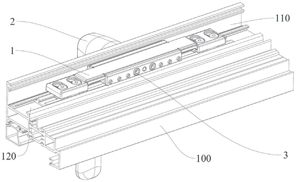
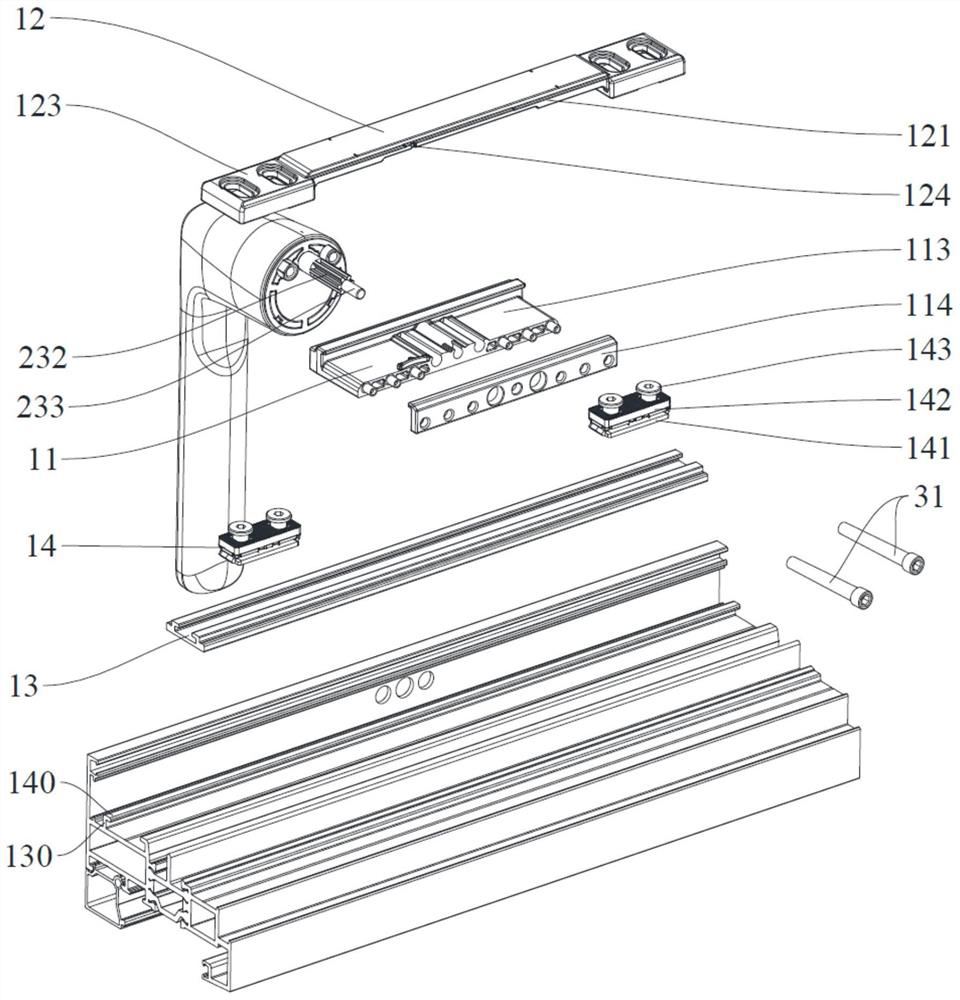
[0156] Refer below Figure 1-Figure 7 and Figure 14-Figure 21 A driving device of a specific embodiment of the present invention will be described.

[0157] The driving device in this embodiment includes a transmission mechanism 1 , a handle 2 and a locking mechanism 3 .

[0158] The transmission mechanism 1 includes a mounting shell 11, a movable part 12 and a connecting assembly 14. The side wall of the mounting shell 11 can be used to abut against the mounting wall 110 of the profile part 100, and the mounting shell 11 can be arranged on the profile part 100. The mounting shell 11 is formed with a sliding groove 111, and the tops of the two side walls of the sliding groove 111 are respectively provided with limiting edges 112, and the limiting edges 112 on the two side walls of the sliding groove 111 are respectively extended in the direction close to the other side wall . The movable part 12 is installed in the sliding groove 111, and the two side walls of the movable ...

Embodiment 2

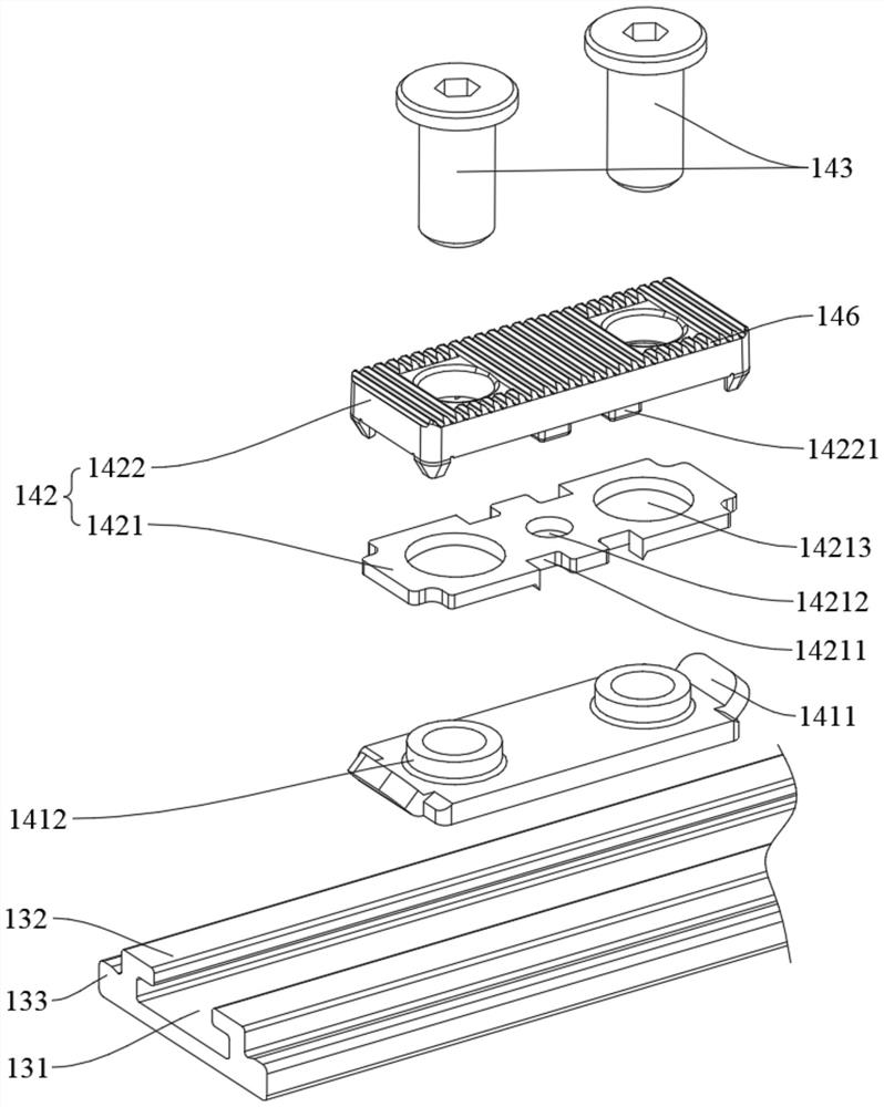
[0169] The structure of the driving device of this embodiment is substantially the same as that of Embodiment 1. The difference between the two is the structure of the connecting assembly 14. Only the difference between the two is described here. The structure of this embodiment is the same as that of Embodiment 1. I won't repeat them here.

[0170] like Figure 8-Figure 12 As shown, the connecting assembly 14 includes a second connecting member 144 and a second fixing member 145 . A fastening protrusion 1443 is disposed on the bottom wall of the second connecting member 144 , and the fastening protrusion 1443 can be used to pass through the matching hole 135 on the transmission member 13 . The second fixing part 145 passes through the first connecting part 123 and connects with the second connecting part 144 . The second connecting member 144 includes a locking end 1441 and a connecting end 1442 . The locking end 1441 can be slidably locked in the profile part 100 . The c...


PUM


Abstract

The invention discloses a driving device. The driving device comprises a transmission mechanism, a lever handle and a locking mechanism. The transmission mechanism comprises an installation shell anda movable piece, a sliding groove is formed in the installation shell, and limiting edges are arranged at the tops of the two side walls of the sliding groove respectively. The movable piece is arranged in the sliding groove in a penetrating manner, and a transmission rack is arranged on the bottom wall of the movable piece. The lever handle comprises a handle body, a fixing base, a connecting shaft and a second fastener, a second mounting groove is formed in one end of the handle body, and an inner tooth part is arranged in the second mounting groove; the fixing base is arranged in the secondmounting groove and can be connected with a profile part; the connecting shaft is rotationally arranged in the fixing base and comprises a first outer tooth part and a second outer tooth part, the first outer tooth part is meshed with the inner tooth part, and the second outer tooth part can be meshed with the transmission rack; one end of the second fastener is connected with the bottom wall ofthe second mounting groove; and the locking mechanism can be arranged in the mounting shell and the mounting wall in a penetrating manner and is connected with the fixing base. The driving device hasa small installation space.

Description

technical field [0001] The invention relates to the technical field of doors and windows, in particular to a driving device. Background technique [0002] The door and window driving structure usually includes a transmission mechanism and a handle, and the movement of the transmission mechanism is driven by the handle to realize the overall transmission of the door and window hardware. In the prior art, a polygonal shaft is often provided on the output end of the handle, and a polygonal groove cooperating with the polygonal shaft is provided on the transmission mechanism that the handle cooperates with. The rotational force of the polygonal shaft can be transmitted to the transmission mechanism by operating the handle rotation, thereby The transmission mechanism can drive the hardware transmission in the door and window device to open and lock. In the process involved, the transmission mechanism not only needs to meet the specified stroke, but also needs to ensure the force...

Claims


Application Information

Patent Timeline
Patent Type & Authority Applications(China)
IPC IPC(8): E05C9/00E05C9/02E05C9/12E05C9/20
CPCE05C9/021E05C9/028E05C9/004E05C9/20E05C9/12E05B1/003E05B15/006
Inventor 李树鹏潘锡勇王双丽
Owner SHENZHEN HOPO WINDOW CONTROL TECH CO LTD
Why Eureka
Try Eureka