Full-automatic low-clearance duct piece conveyor based on binocular vision technology and duct piece conveying method

A binocular vision and fully automatic technology, applied in earthwork drilling, hoisting devices, wellbore lining, etc., can solve problems such as not suitable for low headroom operations, unable to be arranged on tracks, and large three-dimensional space

Active Publication Date: 2020-12-11
ZHENGZHOU UNIVERSITY OF LIGHT INDUSTRY
View PDF5 Cites 0 Cited by
  • Summary
  • Abstract
  • Description
  • Claims
  • Application Information

AI Technical Summary

Problems solved by technology

[0010] The common disadvantages of the above three types of segment conveyors are: the main parts of all existing conveyors cannot be arranged in the same plane as the track mechanism, cannot be arranged in the track, and occupy a large three-dimensional space in the up and down direction, so It is not suitable for low headroom work occasions, and cannot adapt to the industry trend of shield machine miniaturization

Method used


Image

  • Full-automatic low-clearance duct piece conveyor based on binocular vision technology and duct piece conveying method
  • Full-automatic low-clearance duct piece conveyor based on binocular vision technology and duct piece conveying method
  • Full-automatic low-clearance duct piece conveyor based on binocular vision technology and duct piece conveying method

Examples


Embodiment Construction

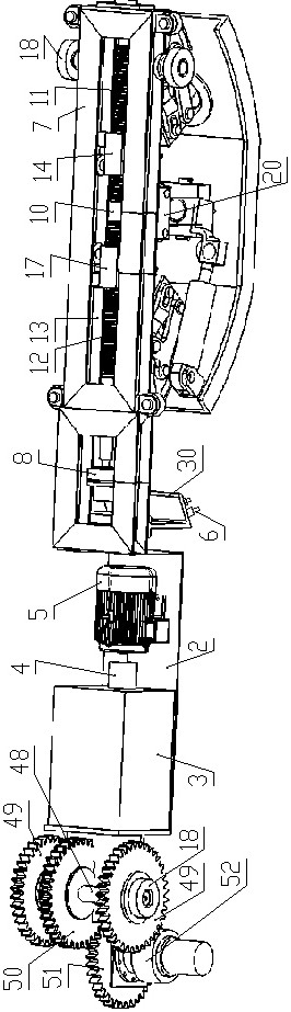
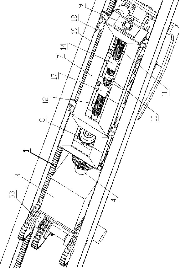
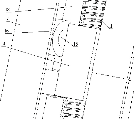
[0083] Such as Figure 1 to Figure 12 As shown, the fully automatic low-clearance segment conveyor based on binocular vision technology of the present invention is used in conjunction with the track arranged on the top of the constructed tunnel, and the track includes two racks 1 arranged parallel and side by side along the length of the tunnel; In the present invention, the width direction of the tunnel is the width direction, and the length direction of the tunnel is the front-rear direction.

[0084] It includes a traveling mechanism, a segment pick-and-place mechanism and a power mechanism for providing power for the travel mechanism and the segment pick-and-place mechanism. The power mechanism includes a fixed plate 2, and a hydraulic tank 3 is installed on the fixed plate 2, and the hydraulic tank 3 is connected to a A hydraulic pump 4 is provided, and the hydraulic pump 4 is connected with an electric motor 5 for driving the hydraulic pump 4, and the electric motor 5 is...


PUM


Abstract

The invention discloses a full-automatic low-clearance duct piece conveyor based on a binocular vision technology. The full-automatic low-clearance duct piece conveyor is matched with a track arrangedat the top of a constructed tunnel for use, and comprises a walking mechanism, a duct piece taking and placing mechanism and a power mechanism for providing power for the walking mechanism and the duct piece taking and placing mechanism; the duct piece taking and placing mechanism comprises a lifting taking and placing device and a binocular camera; the lifting taking and placing device comprisesa long-strip-shaped main rack; a positive and negative rotation hydraulic motor for hoisting is arranged in the main rack, the positive and negative rotation hydraulic motor for hoisting is connectedwith a trapezoidal lead screw, a positive rotation part of the trapezoidal lead screw is in threaded connection with a first moving block, and a negative rotation part of the trapezoidal lead screw is in threaded connection with a second moving block; and the main rack is downwards connected with a mounting plate, and the binocular camera is mounted on the mounting plate. According to the full-automatic low-clearance duct piece conveyor, the main body is installed in the track in the tunnel and located on the same plane with the track, the low-clearance and automatic operation requirements are met, the industrial trend of shield tunneling machine miniaturization is met, and the working efficiency is improved.

Description

technical field [0001] The invention relates to the technical field of shield tunneling, in particular to a segment conveying device. Background technique [0002] The shield machine is widely used in various underground tunnel construction sites around the world due to its high degree of automation, high construction efficiency, small disturbance to the ground, suitable for large depth and long distance operations, and many other advantages. [0003] With the continuous subdivision of the shield machine market, the miniaturization and low headroom operation of the shield machine have become an important development direction. The micro-shield machine can effectively save construction costs, shorten the construction period, and minimize the impact on the geological environment. [0004] During the entire construction process of the shield machine, segment assembly is one of the key processes of the whole set of equipment, and segment transportation is the "stuck neck" proce...

Claims


Application Information

Patent Timeline
Patent Type & Authority Applications(China)
IPC IPC(8): E21D11/08E21D11/40B66F9/06B66F9/075B66F9/18B66F9/20
CPCB66F9/06B66F9/0755B66F9/07572B66F9/18B66F9/20E21D11/08E21D11/40
Inventor 肖艳秋费致根崔光珍房占鹏黄荣杰孙春亚杨先超李培婷
Owner ZHENGZHOU UNIVERSITY OF LIGHT INDUSTRY
Why Eureka
Try Eureka