
Swing rod position calibration device, error elimination method thereof and shift-by-wire actuator

A calibration device and slide bar technology, applied in the direction of transmission control, toothed components, belts/chains/gears, etc., can solve problems such as front and rear interference jamming, motor stall, function failure, etc., to eliminate motion errors Effect

Active Publication Date: 2020-12-11
GUANGZHOU AUTOMOBILE GROUP CO LTD
View PDF4 Cites 0 Cited by
  • Summary
  • Abstract
  • Description
  • Claims
  • Application Information

AI Technical Summary

Problems solved by technology

The stroke deviation of 4.8mm is larger than the reserved margin of 2.5mm, and there is a phenomenon of front and rear interference jamming, which is finally manifested in the actual vehicle as the lack of gear shifting and motor stalling, resulting in functional failure

Method used


Image

  • Swing rod position calibration device, error elimination method thereof and shift-by-wire actuator
  • Swing rod position calibration device, error elimination method thereof and shift-by-wire actuator
  • Swing rod position calibration device, error elimination method thereof and shift-by-wire actuator

Examples


Embodiment Construction

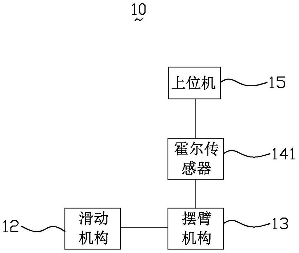
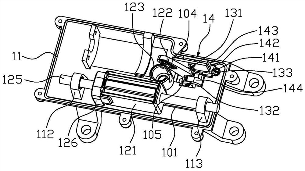
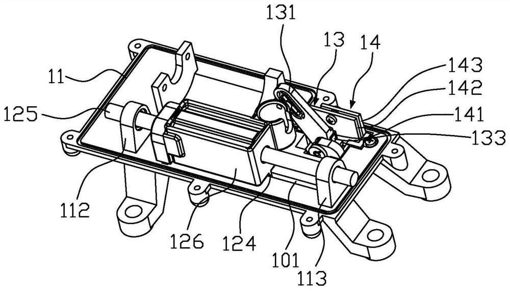
[0030] figure 1 is a schematic diagram of the pendulum position calibration device of the present invention, figure 2 is a partial structural schematic diagram of the pendulum position calibration device of the present invention, image 3 yes figure 2 The structural schematic diagram of the other direction of the pendulum position calibration device shown, Figure 4 yes figure 2 The schematic diagram of the side view structure of the pendulum position calibration device shown, Figure 5 It is a partial cross-sectional schematic diagram of the pendulum position calibration device of the present invention, please refer to Figure 1 to Figure 5 , The swing rod position calibration device 10 includes a frame 11 , a slide mechanism 12 , a swing arm mechanism 13 , a detection mechanism 14 and a host computer 15 .

[0031] The sliding mechanism 12 comprises a slide block 121, a slide bar 125 and a stop block 126, the slide bar 125 is arranged on the frame 11, the slide block ...


PUM


Abstract

The invention discloses a swing rod position calibration device. The swing rod position calibration device comprises a rack, a sliding mechanism, a swing arm mechanism, a detection mechanism and an upper computer; the sliding mechanism comprises a sliding block, a sliding rod and a limiting block, the sliding rod is arranged on the rack, the sliding block is arranged on the sliding rod, the limiting block is detachably arranged on the rack, and the sliding rod passes through the position below the limiting block; the swing arm mechanism comprises a swing arm and a magnetic part, one end of theswing arm is hinged to the rack, the other end of the swing arm is slidably connected to the sliding block, and the magnetic part is connected to the swing arm; the detection mechanism comprises a Hall sensor, the Hall sensor has an EEPROM function, and the Hall sensor is arranged corresponding to the magnetic part; and when the sliding block abuts against the limiting block, the Hall sensor detects a first angle of swinging of the swing arm, the upper computer is used for calibrating the first angle and outputting a calibrated second angle, and the Hall sensor is used for storing the secondangle. The swing rod position calibration device can eliminate the influence of magnetic field deflection angle errors. The invention further relates to a shift-by-wire actuator and a swing rod position error elimination method.

Description

technical field [0001] The invention relates to the technical field of transmission shift control, in particular to a swing rod position calibration device, an error elimination method thereof, and a wire-controlled shift actuator. Background technique [0002] Automobile manipulation and control by wire is a direction of future development. The wire shift actuator is a mechanical and electronic integrated mechanism device used to control the automatic transmission to perform P, R, N, D, S (or other type) gear switch. Moreover, it is often necessary to detect the position of the transmission shift rocker during the control process. [0003] In the traditional technology, a hall sensor is used to cooperate with a magnet to detect the position of the shift rocker, that is, to detect the rotation angle position of the shift rocker. However, due to manufacturing errors in the cutting of the magnet, the magnetic field deflection angle of the magnet is relatively large (-12°<...

Claims


Application Information

Patent Timeline
Patent Type & Authority Applications(China)
IPC IPC(8): F16H59/02
CPCF16H59/0217
Inventor 刘志刚范汉茂
Owner GUANGZHOU AUTOMOBILE GROUP CO LTD
Learn More