
Adaptive Common Optical Path Grating Interferometer and Its Realization Method

A technology of grating interference and common optical path, which is applied in the direction of instruments, optical devices, measuring devices, etc., can solve the problems of not adopting a complete common optical path interferometer design, unable to eliminate the influence of optical path, etc., and achieve the elimination of motion errors, high precision and resolution rate effect

Active Publication Date: 2017-06-13
SHANGHAI INST OF OPTICS & FINE MECHANICS CHINESE ACAD OF SCI
View PDF4 Cites 0 Cited by
  • Summary
  • Abstract
  • Description
  • Claims
  • Application Information

AI Technical Summary

Problems solved by technology

However, the technical solutions represented by the above all have the following problems: no real complete common optical path interferometer design is adopted
Therefore, the influence of the optical path of the above-mentioned motion error cannot be eliminated, but its influence can only be alleviated

Method used


Image

  • Adaptive Common Optical Path Grating Interferometer and Its Realization Method
  • Adaptive Common Optical Path Grating Interferometer and Its Realization Method
  • Adaptive Common Optical Path Grating Interferometer and Its Realization Method

Examples


Embodiment Construction

[0031] The present invention will be further described below in conjunction with the embodiments and accompanying drawings, but the protection scope of the present invention should not be limited thereby.

[0032] 1. Embodiment 1. Such as figure 1 .

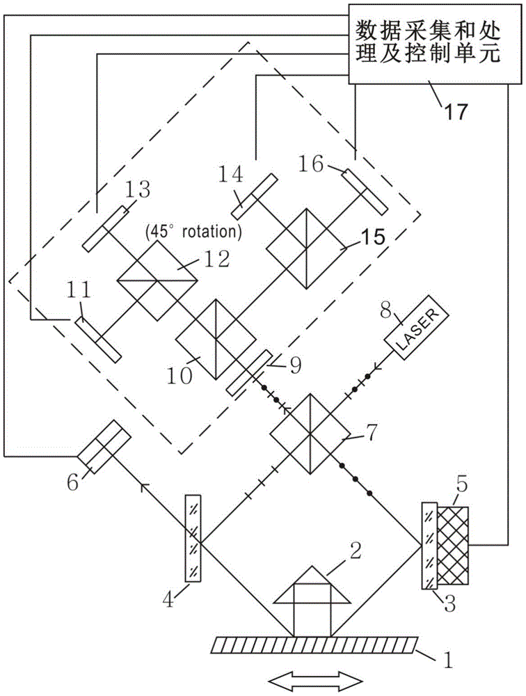
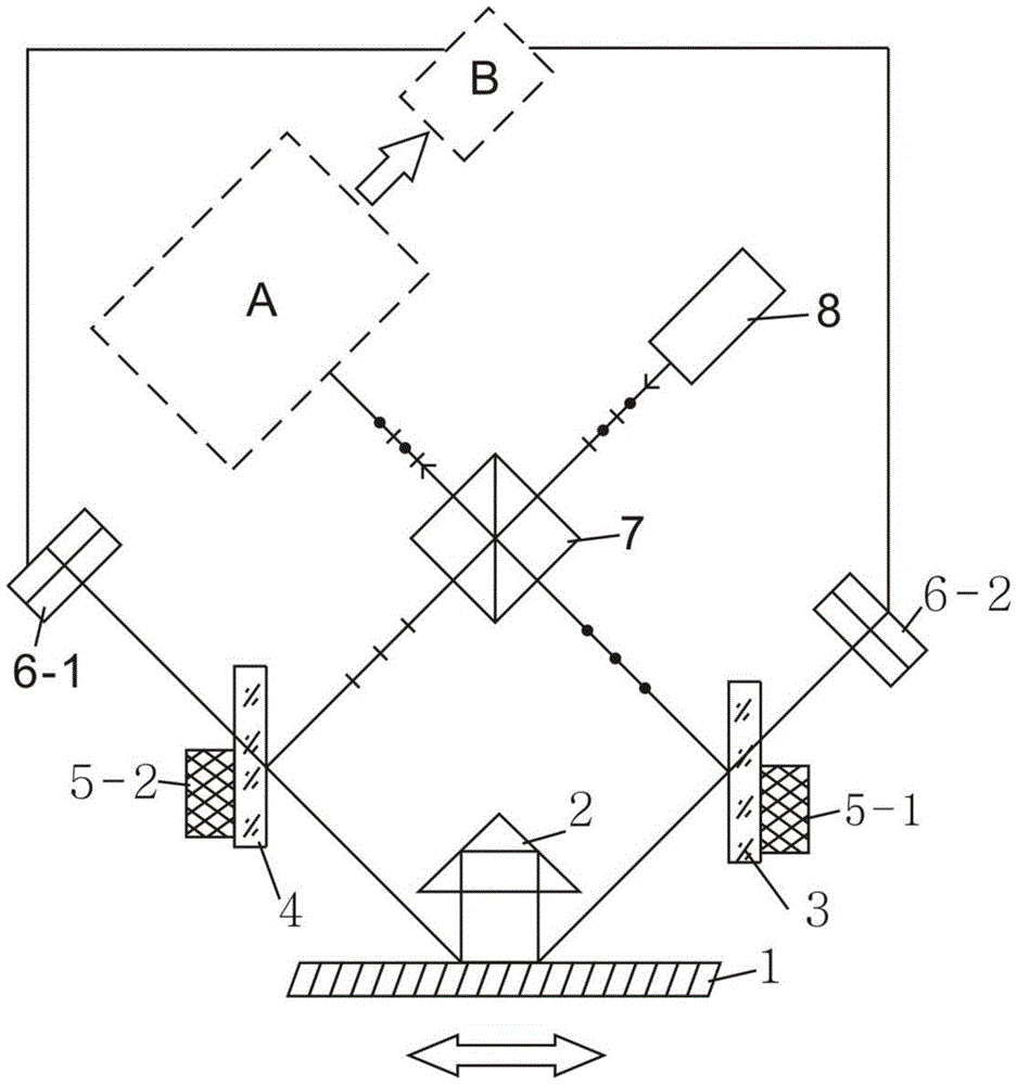
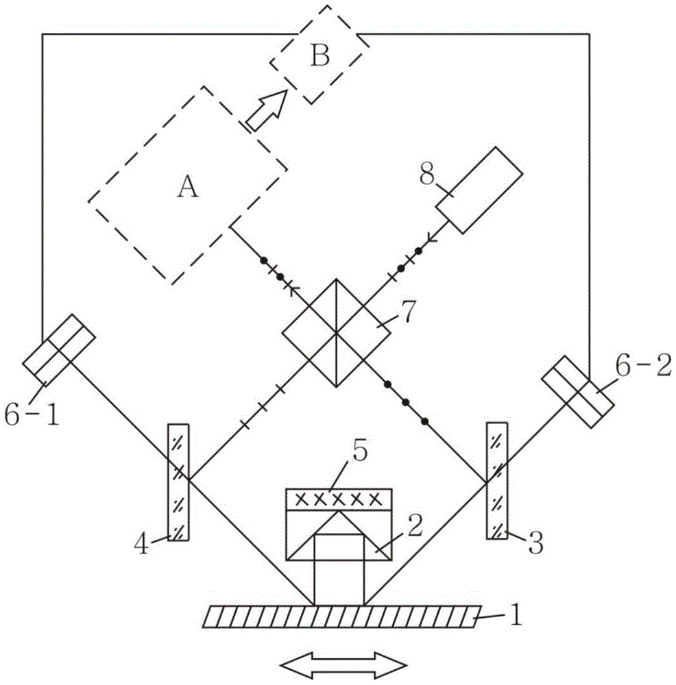
[0033] The laser 8 emits linearly polarized light, which is divided into P light and S light by the first polarizing beam splitter 7, and enters the diffraction grating 1 through the mirror 3 and the mirror 4 respectively, and is diffracted by the diffraction grating 1 (set as ±1-order light The direction of the two diffracted lights of ) is perpendicular to the diffraction grating 1, and after being reflected by the corner cube prism 2, the P light and the S light respectively enter the respective optical paths of the other party (S light and P light), forming a complete common optical path, and then pass through the first polarization Beam splitter 7 emerges as orthogonal linearly polarized light, which enters the dotted line...


PUM


Abstract

An adaptive common optical path grating interferometer, including: a grating ruler with relative motion, a corner cube prism, a mirror, a mirror, a position-sensitive detector, a polarization beam splitter, a linearly polarized light source, and a PZT for driving the mirror A micro-displacement driver, a data acquisition and processing and control unit, a polarization phase-shift interference photodetection unit or a dual-frequency heterodyne interference photodetection unit. The present invention adopts the self-adaptive method of controlling the corner cube prism or reflector based on the position feedback of the diffraction light spot to ensure the complete common optical path characteristics of the dynamic grating interferometer, thereby eliminating the influence of the optical path caused by the relative motion error of the grating scale body, and then obtaining high precision and resolution.

Description

technical field [0001] The invention relates to an optical measuring instrument, in particular to an adaptive common optical path grating interferometer and its realization method. Background technique [0002] The grating interferometer is the core of the high-precision grating ruler measurement system (the grating pitch is generally less than 10 microns), which determines its accuracy and resolution. The high-precision grating ruler measurement system consists of a grating ruler body, a mounting fixture, a reading head based on a grating interferometer, a signal controller and a display, and its function is to measure high-precision displacement. Widely used in machine tool processing control, wafer processing and cutting, integrated circuit lithography equipment, semiconductor testing, robot systems, aerospace, scientific research, military and other fields. [0003] The high-precision grating ruler measurement system is not only one of the most basic modern automatic me...

Claims


Application Information

Patent Timeline
Patent Type & Authority Patents(China)
IPC IPC(8): G01B9/02
Inventor 韦春龙周常河向显嵩卢炎聪
Owner SHANGHAI INST OF OPTICS & FINE MECHANICS CHINESE ACAD OF SCI
Learn More