Method and device for displaying abnormal sound position of vehicle, vehicle-mounted terminal and storage medium

A vehicle-mounted terminal and abnormal noise technology, applied in the field of vehicle safety, can solve problems such as time-consuming and low accuracy

Active Publication Date: 2020-12-11
LAUNCH TECH CO LTD
View PDF4 Cites 2 Cited by
  • Summary
  • Abstract
  • Description
  • Claims
  • Application Information

AI Technical Summary

Problems solved by technology

[0003] In the prior art, the approximate location of the abnormal noise is usually judged by human ear recognition, and then the components installed at the location are d

Method used


Image

  • Method and device for displaying abnormal sound position of vehicle, vehicle-mounted terminal and storage medium
  • Method and device for displaying abnormal sound position of vehicle, vehicle-mounted terminal and storage medium
  • Method and device for displaying abnormal sound position of vehicle, vehicle-mounted terminal and storage medium

Examples


Embodiment 1

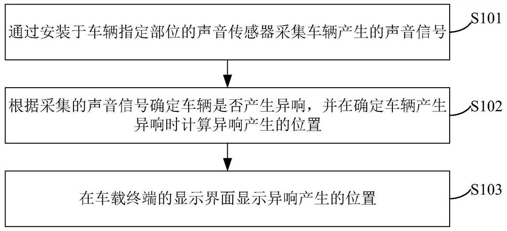
[0087] figure 1 It is a schematic flow chart of the method for displaying the location of the abnormal sound of the vehicle provided in Embodiment 1 of the present application, which may include the following steps:

[0088] S101: Collect the sound signal generated by the vehicle through the sound sensor installed in the designated part of the vehicle.

[0089] The sound sensor is equivalent to a microphone or a microphone, and is used to collect the sound signal generated by the vehicle and display the vibration image of the sound signal, and may include a resistive sound sensor, a capacitive sound sensor and a magnetoelectric sound sensor.

[0090] Wherein the sound sensor installed at the designated part of the vehicle is used to obtain the sound signal generated by the designated part, such as when the method of displaying the position of the abnormal sound of the vehicle is used in the scene of displaying the position of the abnormal sound of the engine in the vehicle, th...

Embodiment 2

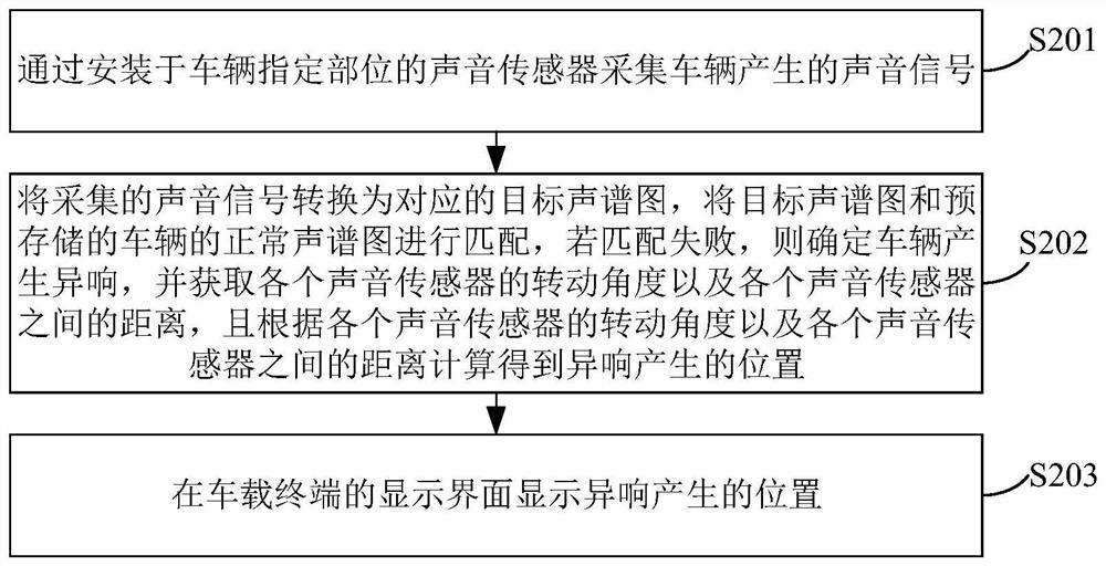
[0104] Figure 2-a The schematic flow chart of the method for displaying the location of abnormal vehicle noise provided in Embodiment 2 of the present application is a further refinement and description of step S102 in Embodiment 1 above. The method may include the following steps:

[0105] S201: Collect the sound signal generated by the vehicle through the sound sensor installed in the designated part of the vehicle.

[0106] Wherein, the above step S201 is the same as the step S101 in the first embodiment, and its specific implementation process can refer to the description of the step S101, which will not be repeated here.

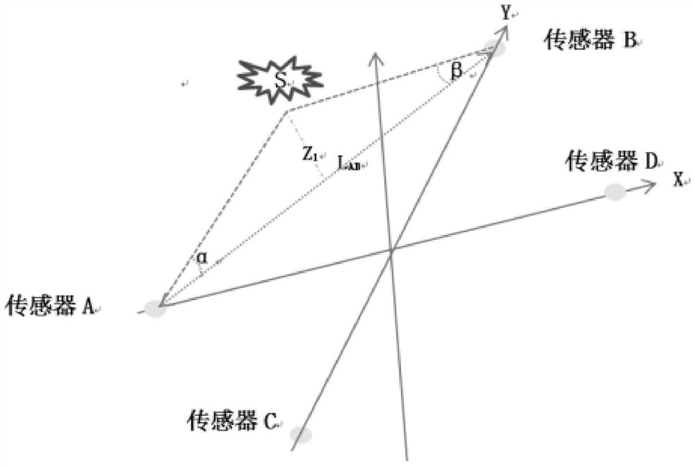
[0107] S202: Convert the collected sound signal into the corresponding target spectrogram, match the target spectrogram with the pre-stored normal spectrogram of the vehicle, if the matching fails, determine that the vehicle produces abnormal noise, and obtain each sound sensor The rotation angle of each sound sensor and the distance between each soun...

Embodiment 3

[0142] image 3 It is a schematic structural diagram of the device for displaying the location of abnormal vehicle noise provided by Embodiment 3 of the present application. For the convenience of description, only the parts related to the embodiment of the present application are shown.

[0143] The device for displaying the position of the abnormal sound of the vehicle may be a software unit, a hardware unit, or a combination of software and hardware built into the vehicle-mounted terminal, or it may be integrated into the vehicle-mounted terminal as an independent pendant.

[0144] The device for displaying the position of abnormal noise of the vehicle is applied to the vehicle terminal, including:

[0145] The collection module is used to collect the sound signal generated by the vehicle through the sound sensor installed in the designated part of the vehicle;

[0146] A calculation module, configured to determine whether the vehicle produces an abnormal sound according t...


PUM


Abstract

The invention is suitable for the technical field of vehicle safety, and provides a method and device for displaying the abnormal sound position of a vehicle, a vehicle-mounted terminal and a storagemedium, and the method for displaying the abnormal sound position of the vehicle comprises the steps: collecting a sound signal generated by the vehicle through a sound sensor installed at a specifiedpart of the vehicle, and determining whether the vehicle generates an abnormal sound according to the sound signal, calculating a position where the abnormal sound is generated when determining thatthe vehicle generates the abnormal sound, and displaying the position where the abnormal sound is generated on a display interface of the vehicle-mounted terminal. According to the invention, the abnormal sound generation position can be quickly and accurately positioned.

Description

technical field [0001] The present application relates to the field of vehicle safety, and in particular to a method, a device, a vehicle-mounted terminal and a storage medium for displaying the position of abnormal noise of a vehicle. Background technique [0002] With the popularization of vehicles, consumers have higher and higher requirements for the comfort of vehicles. As one of the important factors affecting the comfort of vehicles, abnormal noise of vehicles has also attracted widespread attention. [0003] In the prior art, the approximate location of the abnormal noise is usually judged by human ear recognition, and then the components installed at the location are disassembled and diagnosed to determine the specific location of the abnormal noise. However, this method is not only time-consuming but also expensive long and less accurate. [0004] Therefore it is necessary to propose a new technical solution to solve the above technical problems. Contents of the...

Claims


Application Information

Patent Timeline
IPC IPC(8): G01S5/20
CPCG01S5/20
Inventor 刘新梁鑫
Owner LAUNCH TECH CO LTD
Why Eureka
Try Eureka