Method and device for determining deflection angle of ct detector

A determination method and a determination device technology, which are applied in the directions of X-ray equipment, electrical components, computed tomography scanners, etc., can solve the problems of image artifacts, affecting the interpretation of CT reconstruction images, etc.

Active Publication Date: 2015-10-28
INST OF PROCESS ENG CHINESE ACAD OF SCI
View PDF2 Cites 0 Cited by
  • Summary
  • Abstract
  • Description
  • Claims
  • Application Information

AI Technical Summary

Problems solved by technology

When this condition cannot be satisfied, that is, when the detector rotates around the projection point of the rotation center and deviates from an angle, and the deflection angle is large, even if the COR is corrected, the image reconstructed according to the standard algorithm will still have artifacts. Interpretation of CT reconstruction images

Method used


Image

  • Method and device for determining deflection angle of ct detector
  • Method and device for determining deflection angle of ct detector
  • Method and device for determining deflection angle of ct detector

Examples


no. 1 example

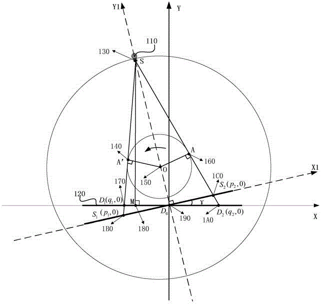
[0058] exist figure 1 A schematic diagram of the geometric relationship of relevant parameters in the CT scan of the first embodiment of the present invention is shown in . in, figure 1 The CT machine in the third-generation fan-beam scanning mode is shown in . Such as figure 1 As shown, the third-generation CT includes a radiation source 110 and a detector array 120, wherein the emission signal of the radiation source 110 has a certain opening angle, a typical opening angle range is 30-45°, and the detector array 120 is arranged on the ray Within the sector angle covered by the signal emitted by the source 110 , the detector array 120 includes a plurality of detector units, and each detector unit is a detector pixel. During scanning, the radiation source 110 and the detector array 120 rotate around the rotation center O, 150 synchronously. Wherein, a straight line passing through the focal point S, 130 of the ray source 110 and perpendicular to the detector array 120 inte...

no. 2 example

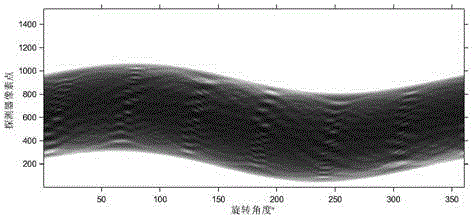
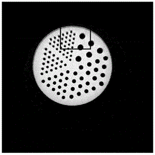
[0104]On the basis of the foregoing embodiments, in this embodiment, the third-generation equidistant fan-beam CT is used as the CT to be tested. The high-voltage generator of the ray source system is produced by Yxlon in Germany, the model is MGG40, the X-ray tube is produced by Philips (Philips), the model is Y-TU / 100-D01; the detector is Anbangshi ( The equidistant array produced by Beijing) Technology Co., Ltd., the model is LSC-412, the scintillator material is GOS (Gadolinium Oxysulfide, gadolinium oxysulfide), and the detector array has a total of 1536 detector units, that is, 1536 detector pixels. The dot size is 0.3*0.6mm, and the pixel pitch is 0.4mm. The x-ray working voltage used in this experiment is 100kVp, the current is 2.2mA, the stepper motor drives the stage, rotates 360° for sampling, and the incremental step of sampling angle is 0.1°. The measured object adopts the porous plexiglass model. The reconstruction algorithm adopts standard FBP algorithm, using...

no. 3 example

[0123] Figure 8 It is a structural diagram of a device for determining the rotation angle of a CT detector according to the third embodiment of the present invention. Such as Figure 8 As shown, the device includes:

[0124] The edge projection point position acquisition unit 81 is used to scan the entire circumference of the object under test using the CT to be measured, and obtain the first limit position D of the edge projection point of the object under test in the detector array 1 and the second extreme position D 2 ;

[0125] The edge projection point coordinate acquisition unit 82 is used to project the position D of the center of rotation of the CT to be measured COR in the detector array 0 As the origin, take the straight line where the detector array is located as the X-axis, establish a coordinate system, and calculate D 1 The X-axis coordinate value q 1 and D 2 The X-axis coordinate value q 2 ;

[0126] The distance calculation unit 83 is used to calculat...


PUM


Abstract

Disclosed are a method and an apparatus for determining the deflection angle of a CT detector. The method comprises: fully scanning an object being detected using a CT to be detected to obtain a first extreme position D1 and a second extreme position D2 in a detector array of the edge projection points of the object being detected (210); establishing a coordinate system by using a position D0 in the detector array of the projection point of the rotation centre COR of the CT to be detected as the origin, using the line where the detector array is located as the X-axis and calculating the coordinate value q1 of D1 and the X-axis coordinate value q2 of D2 (220); calculating the distance RD between the ray source focus of the CT to be detected and D0 (230); and determining the deflection angle γ of the CT detector to be detected according to RD, q1 and q2 (240). The determination method and apparatus do no need to use a dedicated calibration motif and can determine the deflection angle of a CT detector to be detected just by directly scanning an object to be detected and simply operating the acquired original data.

Description

technical field [0001] The invention relates to the technical fields of medical digital imaging and non-destructive testing, in particular to a method and a device for determining the deflection angle of a CT detector. Background technique [0002] CT (Computed Tomography, computerized tomography) was first used in medical imaging, and was later introduced into the field of industrial non-destructive testing. Due to its non-intrusive and non-interfering detection characteristics, CT has also been well received in the fields of agriculture, forestry, geophysics, and chemical industry. Applications. CT can be divided into five generations according to the data acquisition methods of the ray source-detector movement. At present, the more commonly used ones are the first-generation pencil beam scanning mode of translation-rotation and the third-generation fan beam scanning mode of rotation-rotation. Among them, the third-generation fan-beam scanning mode is divided into two typ...

Claims


Application Information

Patent Timeline
Patent Type & Authority Patents(China)
IPC IPC(8): A61B6/03G01N23/04H05G1/26
CPCA61B6/03A61B6/032
Inventor 孟凡勇李忠传李静海
Owner INST OF PROCESS ENG CHINESE ACAD OF SCI
Why Eureka
Try Eureka