High bandwidth oscilloscope

a high-bandwidth, oscilloscope technology, applied in the field of digital oscilloscopes, can solve the problems of inability to use a suitable technique, compromise the accuracy of digitized waveforms, mismatched digitizers, etc., and achieve the effect of improving the bandwidth of the oscilloscope and enhancing the bandwidth

Inactive Publication Date: 2007-05-15
TELEDYNE LECROY
View PDF19 Cites 50 Cited by
  • Summary
  • Abstract
  • Description
  • Claims
  • Application Information

AI Technical Summary

Benefits of technology

[0012]A method for improving bandwidth of an oscilloscope involves, in preferred embodiments, use of frequency up-conversion and down-conversion techniques to achieve a system bandwidth that significantly exceeds the bandwidth attainable through interleaving alone. In an illustrative embodiment the technique involves separating an input signal into a high frequency content and a low frequency content, down-converting the high frequency content in the analog domain so that it may be processed by the oscilloscope's analog front end, digitizing the low frequency content and the down-converted high frequency content, and forming a digital representation of the received analog signal from the digitized low frequency content and high frequency content. The digital representation is formed in various implementations by up-converting the content to its original frequency band and then recombining the high frequency content with the low frequency content. In preferred implementations this is achieved by passing the high frequency content through a high pass filter, mixing that content with a sinusoidal waveform to generate higher and lower frequency images, substantially eliminating the higher frequency image with a low pass filter, digitizing and upsampling the lower frequency image, mixing the digitized and upsampled content with a periodic waveform having substantially the same frequency as the sinusoidal waveform to generate higher and lower frequency images, and then combining the higher frequency image with the low frequency content to form a digital representation of the original input waveform. In this manner preferred embodiments achieve the significant advantage that bandwidth may be enhanced beyond the limits associated with interleaving and the state of the art in amplifier and ADC design.
[0013]Also disclosed herein is an artifact signal correction system that in preferred embodiments is used to compensate for error tones generated during interleaving. The artifact signal correction system may include a mixing component to generate a waveform corresponding to an artifact such as an error tone, whereupon that waveform may be combined with the input waveform to substantially eliminate the artifact. In one embodiment, an input waveform and a periodic digital waveform are fed into a mixer to generate a mixed waveform with substantially the same frequency content as the input waveform except that the frequency is reversed and the phase content is negative. The periodic digital waveform may be synchronized to the digitizing elements such that the waveform has a positive magnitude during portions of the waveform sampled by a first digitizing element and a negative magnitude during portions of the waveform sampled by a second digitizing element. The mixed waveform may then be input to a digital filter that converts the phase and amplitude of the error tone to substantially the same phase and amplitude of the corresponding tones in input waveform. The converted and mixed waveform may then be synchronized with the input waveform by applying a delay to the input waveform that accommodates the aforementioned mixing and converting operations. An inverted version of the mixed waveform may then be added to the input waveform so as to substantially reduce or eliminate the error tones.

Problems solved by technology

However, such a sampling scope presupposes a repetitive input signal so that the representation of the waveform can be generated over many triggers.
This technique may be unsuitable where the signal that is to be analyzed is not repetitive.
When digitizers are mismatched in these characteristics the accuracy of the digitized waveform is compromised.
One symptom of mismatched digitizers is error signal generation.
These spurious tones serve to degrade the quality of the digitizing system, as measured with the aforementioned specifications.
These and other design issues impose practical restrictions on the degree or order of interleaving used in digital oscilloscopes.
The performance of the amplifiers and samplers, however, is generally limited by the state of the art in integrated circuit fabrication.

Method used


Image

  • High bandwidth oscilloscope
  • High bandwidth oscilloscope
  • High bandwidth oscilloscope

Examples


Embodiment Construction

[0045]The following description details certain operational and structural aspects of various preferred implementations and discusses related design considerations. These implementation details are intended to be illustrative and not limiting. Unless expressly stated otherwise, it should be understood that the components and design approaches described below may be modified to suit other particular applications.

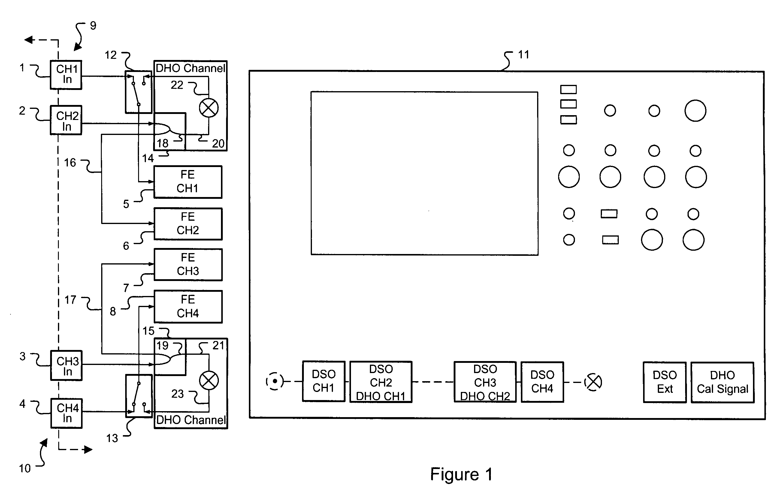
[0046]FIG. 1 shows a digital oscilloscope [11] oscilloscope having four input channels CH1 [1], CH2 [2], CH3 [3], and CH4 [4] connected to the inputs to each of four front-ends [5] [6] [7] [8]. In accordance with the embodiments described herein, the oscilloscope [11] may be configured to digitize waveforms at sample rates of up to 20 GS / s at bandwidths up to 6 GHz into memories up to 50 Mpoints long. Channels 1 [1] and 2 [2] are grouped together into a channel 1 / 2 grouping [9] and channels 3 [3] and 4 [4] are grouped together in a channel 3 / 4 grouping [10]. In the channel 1 / ...


PUM


Abstract

A method for improving bandwidth of an oscilloscope involves, in preferred embodiments, the use of frequency up-conversion and down-conversion techniques. In an illustrative embodiment the technique involves separating an input signal into a high frequency content and a low frequency content, down-converting the high frequency content in the analog domain so that it may be processed by the oscilloscope's analog front end, digitizing the low frequency content and the down-converted high frequency content, and forming a digital representation of the received analog signal from the digitized low frequency content and high frequency content.

Description

CROSS-REFERENCE TO RELATED APPLICATIONS[0001]This application claims the benefit of i) U.S. Provisional Patent Application 60 / 629,050, filed Nov. 18, 2004 by Pupalaikis and entitled “High Bandwidth Oscilloscope,” ii) U.S. Provisional Patent Application 60 / 656,865, filed Feb. 25, 2005 by Pupalaikis et al. and entitled “The Digital Heterodyning Oscilloscope,” and iii) U.S. Provisional Patent Application 60 / 656,616, filed Feb. 25, 2005 by Mueller et al. and entitled “Method and Apparatus for Spurious Tone Reduction in Systems of Mismatched Interleaved Digitizers.” This application is also a continuation-in-part of U.S. patent application Ser. No. 10 / 693,188, filed Oct. 24, 2003 by Pupalaikis et al. and entitled “High Bandwidth Real Time Oscilloscope,” now U.S. Pat. No. 7,058,548, which claims the benefit of U.S. Provisional Patent Application 60 / 420,93 7, filed Oct. 24, 2002 by Pupalaikis et al. and entitled “High Bandwidth Real Time Oscilloscope.”TECHNICAL BACKGROUND[0002]A digital os...

Claims


Application Information

Patent Timeline
Patent Type & Authority Patents(United States)
IPC IPC(8): G01R23/00G16Z99/00
CPCG01R13/0272H03M1/60H03M1/121G06F17/40G16Z99/00G01R13/02G01R19/25H05K999/99
Inventor PUPALAIKIS, PETER J.GRAEF, DAVID C.
Owner TELEDYNE LECROY
Why Eureka
Try Eureka