Apparatus and method for measuring thermal conductivity

a technology of thermal conductivity and apparatus, applied in the field of apparatus and methods for measuring the thermal conductivity of specimens, can solve the problems of only measuring the average value of disk-shaped specimens, unable to meet the requirements of thermal conductivity measurement of regions or features, and the method may work only on low thermal conductivity materials, etc., to achieve accurate measurement of thermal conductivity, reduce lateral heat flow, and improve the effect of accuracy

Inactive Publication Date: 2006-10-05
CAHILL DAVID GERARD
View PDF8 Cites 47 Cited by
  • Summary
  • Abstract
  • Description
  • Claims
  • Application Information

AI Technical Summary

Benefits of technology

[0006] Accordingly, the above-identified shortcomings of existing apparata and methods are overcome by embodiments of the present invention. This invention relates to apparata and method for accurate and micro-scale measurements of thermal properties, so that, if desired, an image of the distribution of thermal conductivity of micro-scale regions may be obtained therefrom. Embodiments of this invention comprise apparatus and method that require no laborious procedure or sample preparation, that are able to measure both bulk metallographic specimens and thin film specimens, that are able to measure thin film specimens on both opaque and transparent substrates, that are able to measure thin film specimens with a thickness greater than about thirty nanometers, that are able to measure specimens of both high and low thermal conductivity from metals to semiconductors to ceramics to polymers, that are able to measure thermal conductivity at a spatial resolution of better than five micrometers, that are able to measure the thermal conductivity at a very high accuracy within ten percent variation from well-accepted handbook values. The embodiments of the apparatus and method of this invention allow measurements of thermal conductivity to be made more reliably, accurately, conveniently and easily than currently possible. Embodiments of this invention allow images of thermal conductivity to be collected from specimens conveniently to show the distribution or variation in the micro-scale. Furthermore, embodiments of this invention can be designed so they are used to perform high throughput measurements of combinatorial specimens to aid the discovery of new materials such as, but not limited to, thermoelectric materials and thermal barrier coatings. Finally, embodiments of this invention may serve as a research tool to examine the dependence of thermal conductivity on composition and phases, to study order-disorder transitions, and to study site preference of chemical elements in intermetallic compounds.
[0007] Several key embodiments of the present invention enable very accurate measurements of thermal conductivity at micrometer-scale resolution and at a very high measurement speed. Firstly, a transducer film such as a thin Al film is deposited onto a specimen to serve as a transducer to absorb laser pulses and enable sensitive measurements of the temperature change through the relatively large thermoreflectance of the transducer film at the wavelength range of about 740 to about 840 nanometers. Secondly, a mode-locked pulsed laser in the femtosecond frequency range is employed. The laser beam is split into two beams, the pump / heat beam and the probe beam. The pump beam is used to heat the near surface region of the transducer film and the probe beam to sense the thermoreflectance of the transducer film. As the heat diffuses through the transducer film to the specimen, the surface temperature of the transducer film decays and so does reflectivity of the transducer film, which is monitored by the probe beam. By varying the time delay between the pump beam and the probe beam, it is possible to access to the short time thermal response (on the order of 100 picoseconds) that is not accessible with the continuous wave lasers. Thirdly, the pump beam is modulated at about 10 MHz to limit lateral heat flow and the probe beam is modulated at audio frequencies to eliminate artifacts created by scattering of the pump beam by surface roughness. The selection of these modulation frequencies make the measurements more reliable. Fourthly, a new, more accurate thermal model that takes into account the entire three-dimensional heat flow in cylindrical coordinates and takes into account a minimum of three layers (the transducer film, the interface between the specimen and the transducer film, and the specimen) enables more accurate thermal conductivity data extraction. Lastly, the thermal effusivity, the square root of the product of the thermal conductivity, Λ, and heat capacity per unit volume, C, is extracted from the ratio of in-phase to out-of-phase voltage of the rf lock-in amplifier, Vin(t) / Vout(t), at the modulation frequency of the pump beam. The thermal properties of the specimen are evaluated by matching the temperature decay obtained from experiment with that calculated from heat flow models. The use of Vin(t) / Vout(t) is much more reliable and robust than the phase lag of a continuous wave probe beam, Vin(t), Vout(t) (without taking the ratio), or the relative intensity of the probe beam to the pump beam. These embodiments together with other embodiments of this invention make it possible to perform micro-scale measurements at about 3.5 micrometer resolution, ninety percent accuracy relative to the well accepted values, and a speed of more than 10,000 measurements per hour in mapping.
[0008] The embodiments of the present invention use a front heating—front sensing, one-sided approach which makes it possible to make measurements conveniently on both bulk specimens and thin film specimens. The thin film specimen can be on any substrate, opaque or transparent, either metallic, semiconductor, ceramic, or polymeric. The thickness of the thin film specimen can be as thin as about 30 nanometers. The embodiments of the present invention, especially the new, more reliable thermal model enable measurements to be made as accurately as or even more accurately than the two-sided approach that is very difficult to perform and too restrictive in specimen geometry.

Problems solved by technology

The method can only measure the average value of the disk-shaped specimen and is unsuitable for measurements of thermal conductivity of regions or features that are on the scale of micrometers.
The method may work only for low thermal conductivity materials when the lateral heat flow and the interface effects are small.
But, even for the low conductivity glass, the method is not accurate as demonstrated by the data shown in Table I of the aforementioned US patent.
For high thermal conductivity materials such as metals, the short time thermal response (on the order of 100 picoseconds) is critical for accurate thermal property assessment, but that time scale is not accessible with continuum wave lasers.
Therefore, accuracy of the data obtained from the aforementioned method is poor.
Therefore, these two apparata put severe constraints on the geometries of the materials that are to be measured.
The two-sided approach is simpler in mathematical equations to evaluate the thermal properties; however, the alignment of the beams for the two-sided measurement is laborious and extremely difficult.
These current apparata and methods have significant drawbacks: 1) the one-sided method has poor accuracy; 2) the two-sided methods put severe constraints on the specimen geometries; and, 3) all the aforementioned methods are suitable to only limited types of materials such as low conductivity materials.

Method used


Image

  • Apparatus and method for measuring thermal conductivity
  • Apparatus and method for measuring thermal conductivity
  • Apparatus and method for measuring thermal conductivity

Examples


Embodiment Construction

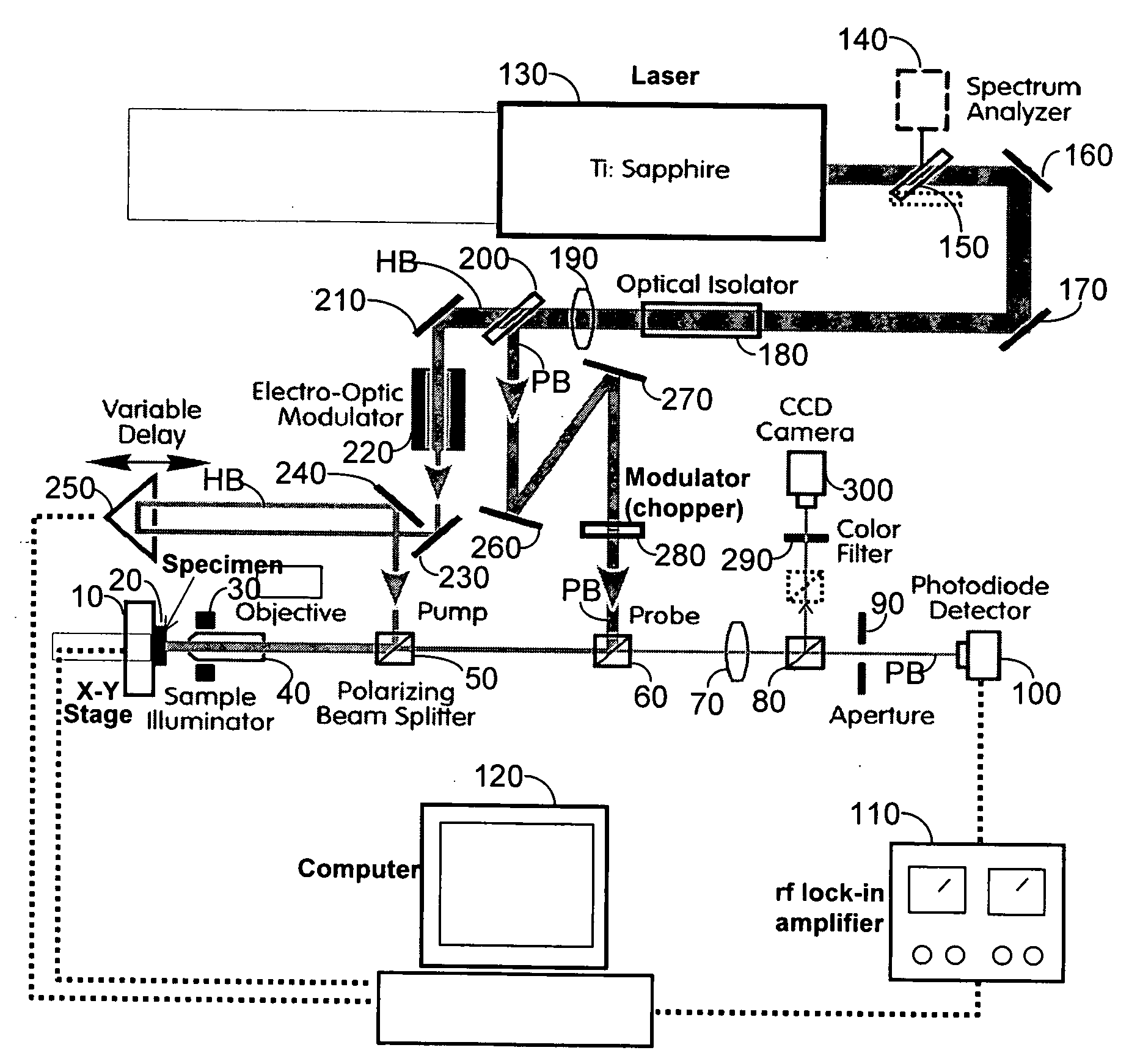
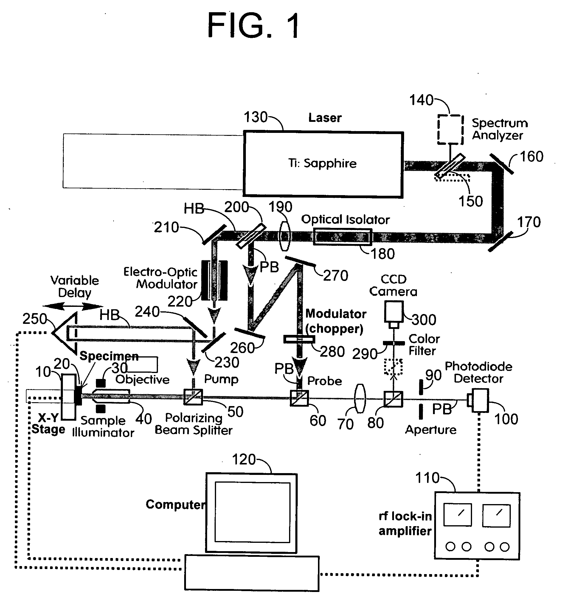
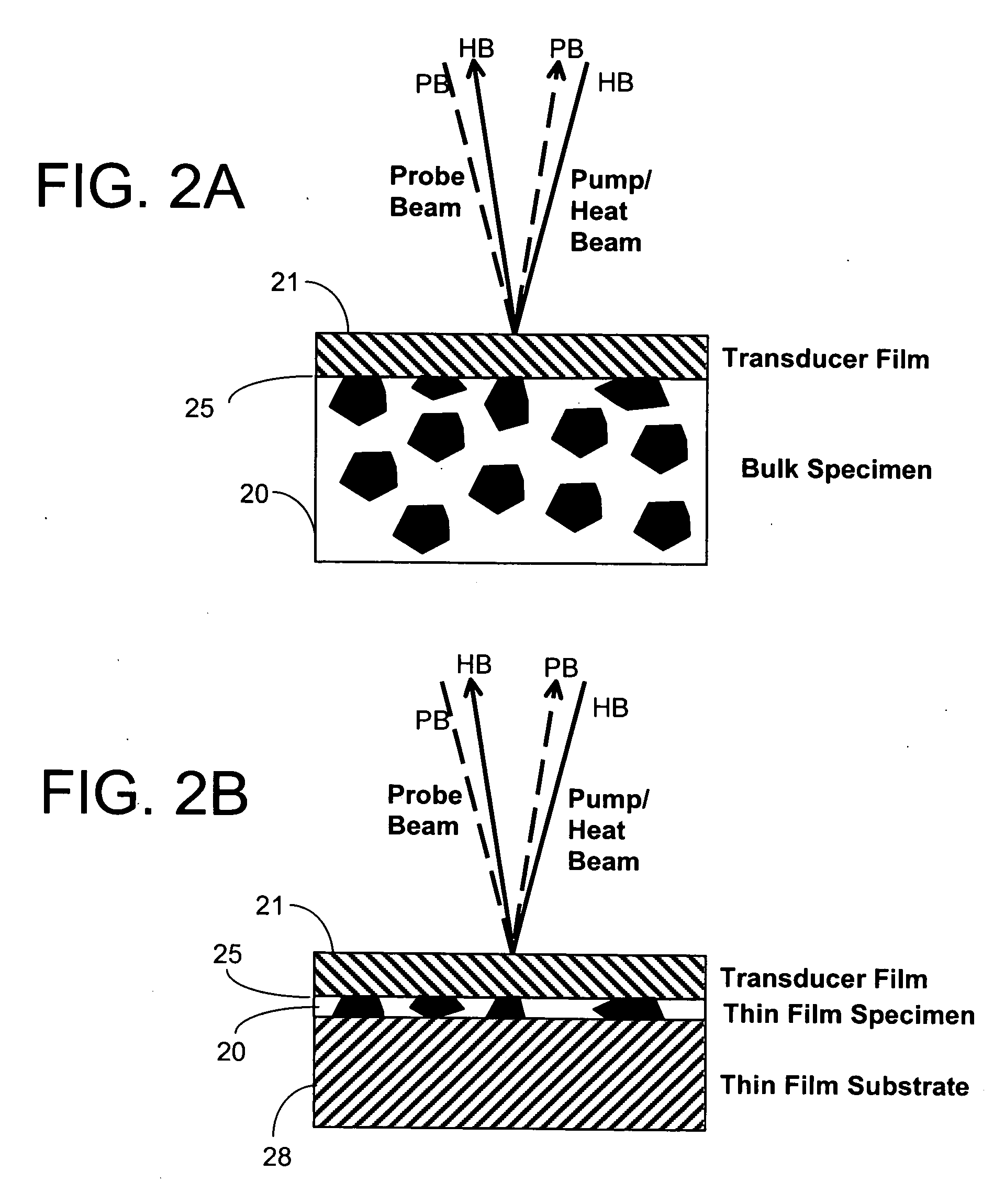
[0017] For the purposes of promoting an understanding of the invention, reference will now be made to some preferred embodiments of the present invention as illustrated in FIGS. 1 and 2, and specific language used to describe the same. The terminology used herein is for the purpose of description, not limitation. Specific components and their functional details disclosed herein are not to be interpreted as limiting, but merely as a basis for the claims as a representative basis for teaching one skilled in the art to various employments of the present invention. Any modifications or variations in the depicted apparatus and method, and such further applications of the principles of the invention as illustrated herein, as would normally occur to one skilled in the art, are considered to be within the spirit of this invention.

[0018] The present invention comprises a method for thermal conductivity measurements in micro-scale. The method comprises: [0019] 1) providing a specimen 20, the...


PUM

PropertyMeasurementUnit
thicknessaaaaaaaaaa
wavelengthaaaaaaaaaa

Abstract

An apparatus and method for measuring and mapping thermal conductivity and thermal diffusivity at micrometer scale resolution. The apparatus and method utilize a mode-locked femtosecond pulsed laser in a pump-probe configuration to analyze time-domain thermoreflectance of a specimen to evaluate its thermal conductivity in micro-scale, so that, if desired, an image of thermal conductivity distribution of micro-scale regions may be obtained therefrom. A multi-layer, complete three-dimensional model that takes into account the entire three-dimensional heat flow in cylindrical coordinates enables micro-scale measurements to be made at an accuracy of about 90% of well-accepted values.

Description

FIELD OF THE INVENTION [0001] The present invention relates generally to apparata and methods for measuring the thermal conductivity of a specimen, specifically, a metal, semiconductor, ceramic or polymer specimen. More specifically, the present invention relates to apparata and methods that utilize a mode-locked femtosecond pulsed laser in a pump-probe configuration to analyze time-domain thermoreflectance of a specimen to evaluate its thermal conductivity in the micro-scale, so that, if desired, an image of thermal conductivity distribution of micro-scale regions may be obtained therefrom. BACKGROUND OF THE INVENTION [0002] The laser flash method is well established and widely used for thermal conductivity measurements. The method requires a disk-shaped specimen having a thickness greater than 1 millimeter and a diameter typically of 10 millimeters. The method can only measure the average value of the disk-shaped specimen and is unsuitable for measurements of thermal conductivity ...

Claims


Application Information

Patent Timeline
Patent Type & Authority Applications(United States)
IPC IPC(8): G01N25/18
CPCG01N25/18
Inventor CAHILL, DAVID GERARD
Owner CAHILL DAVID GERARD
Why Eureka
Try Eureka