Movement control method and device of robot and robot

A control method and robot technology, which can be used in non-electric variable control, two-dimensional position/channel control, motor vehicles, etc., and can solve problems such as increasing the cost of hardware equipment, prone to rollover, and severe robot turbulence.

Pending Publication Date: 2020-12-11
RAJAX NETWORK &TECHNOLOGY (SHANGHAI) CO LTD
View PDF0 Cites 2 Cited by
  • Summary
  • Abstract
  • Description
  • Claims
  • Application Information

AI Technical Summary

Problems solved by technology

[0004] However, the inventor found in the process of realizing the present invention that the above-mentioned methods in the prior art have at least the following defects: in the first method, additional guide rails need to be added, thereby significantly increasing the cost of hardware equipment
In the second method, the robot is controlled to perform a steering operation so that the robot goes straight to the target position. On the one hand, in the steering operation, the robot often needs to rotate a large angle at a time, which makes the robot bump violently and is prone to rollover and other accidents. , especially for load-carrying robots, the accident rate is higher; on the other hand, in the process of going straight after the steering operation, due to the influence of control errors, the robot may deviate from the route, so that the robot cannot reach the designated target position

Method used


Image

  • Movement control method and device of robot and robot
  • Movement control method and device of robot and robot
  • Movement control method and device of robot and robot

Examples


Embodiment Construction

[0099] Exemplary embodiments of the present invention will be described in more detail below with reference to the accompanying drawings. Although exemplary embodiments of the present invention are shown in the drawings, it should be understood that the invention may be embodied in various forms and should not be limited to the embodiments set forth herein. Rather, these embodiments are provided for more thorough understanding of the present invention and to fully convey the scope of the present invention to those skilled in the art.

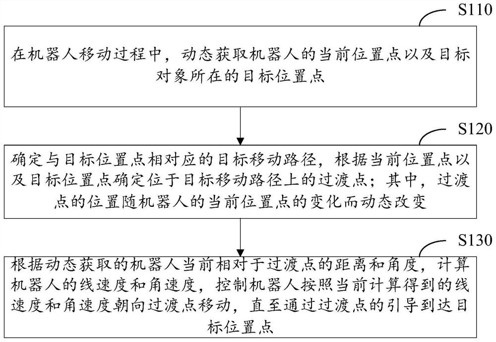
[0100] figure 1 A flow chart of a robot movement control method provided by an embodiment of the present invention is shown. Such as figure 1 As shown, the method includes the following steps:

[0101] Step S110: During the moving process of the robot, dynamically acquire the current location of the robot and the target location where the target object is located.

[0102] Wherein, since the position of the robot is constantly changing durin...


PUM


Abstract

The invention discloses a movement control method and device of a robot and the robot. The method comprises the steps of dynamically acquiring a current position point of a robot and a target positionpoint where a target object is located; determining a target moving path corresponding to the target position point, and determining a transition point located on the target moving path according tothe current position point and the target position point; calculating the linear speed and the angular speed of the robot according to the dynamically obtained distance and angle of the robot relativeto the transition point at present, and controlling the robot to move towards the transition point according to the linear speed and the angular speed obtained through calculation at present until the robot reaches the target position point through the guidance of the transition point. By means of the mode, the transition point can be dynamically adjusted in real time according to the current position of the robot in the moving process, the linear speed and the angular speed of the robot are dynamically adjusted accordingly, and therefore the problem of robot route deviation caused by controlerrors can be effectively prevented.

Description

technical field [0001] The invention relates to the field of robot control, in particular to a robot movement control method, device and robot. Background technique [0002] With the increasing popularity of intelligence, robots have been more and more widely used in various industries. For example, sweeping robots can bring a lot of convenience to users' daily life. During the working process of the robot, it is often necessary to move precisely to the specified target position. For example, when a sweeping robot is charging through a charging pile, it needs to move accurately to the location of the charging pile. [0003] In the existing robot movement control methods, the following two methods are usually adopted: In the first control method, in order to ensure that the robot can accurately dock with the target object at the target position, guide rails are set around the target object in advance, so as to control The robot moves to the vicinity of the guide rail, and ...

Claims


Application Information

Patent Timeline
Patent Type & Authority Applications(China)
IPC IPC(8): G05D1/02
CPCG05D1/0214G05D1/0221G05D1/0223G05D1/0225G05D1/024G05D1/0242G05D1/0257G05D1/0276G05D1/028G05D2201/02
Inventor 吴垒闵伟张金钟邓旻鹏戴新宇
Owner RAJAX NETWORK &TECHNOLOGY (SHANGHAI) CO LTD
Why Eureka
Try Eureka