A medical retractable gynecological medicine chair
A medicine chair and gynecological technology, applied in dental chairs, medical science, dentistry, etc., can solve the problems of not being able to assist gynecology, medicine, etc.
- Summary
- Abstract
- Description
- Claims
- Application Information
AI Technical Summary
Problems solved by technology
Method used
Image
Examples
Embodiment 1
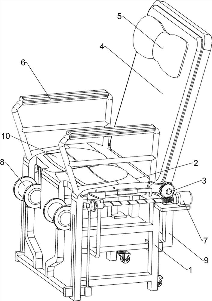
[0029] A medical retractable gynecological medicine chair, such as figure 1 , figure 2 and Figure 7 As shown in the figure, it includes outrigger 1, seat plate 2, rotating shaft 3, back plate 4, headrest 5 and armrest 6. A seat plate 2 is connected between the front and rear outriggers 1, and the right side of the seat plate 2 is rotatably connected with a The rotating shaft 3 is connected with a backing plate 4, the upper left side of the backing plate 4 is connected with a headrest 5, and the front and rear sides of the top of the seat plate 2 are connected with armrests 6, and also include an adjusting mechanism 7 and a supporting mechanism 8. An adjustment mechanism 7 is arranged between the seat plate 1 and the seat plate 2 , and a support mechanism 8 is arranged between the seat plate 2 and the adjustment mechanism 7 .
[0030] The adjustment mechanism 7 includes a motor 71, a screw 72, a worm 73 and a worm wheel 74. The front and rear sides of the inner left side wa...
Embodiment 2
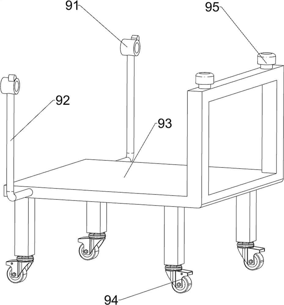
[0034] On the basis of Example 1, as image 3 As shown, it also includes a protection assembly 9, the protection assembly 9 includes a threaded sleeve 91, an L-shaped connecting rod 92, a moving frame 93, a walking wheel 94 and a buffer pad 95, and the two screws 72 are connected with a threaded sleeve 91 through threads. , an L-shaped connecting rod 92 is connected to the threaded sleeve 91, a movable frame 93 is slidably connected between the legs 1 on both sides, and the movable frame 93 is connected with the L-shaped connecting rod 92. The two traveling wheels 94 and the front and rear sides of the top of the moving frame 93 are connected with buffer pads 95 , and the buffer pads 95 are matched with the backing plate 4 .
[0035] When the screw 72 rotates, the threaded sleeve 91 moves to the right, and the threaded sleeve 91 moves to the right through the L-shaped connecting rod 92 to drive the moving frame 93 to move to the right. The traveling wheel 94 can assist the mov...
Embodiment 3
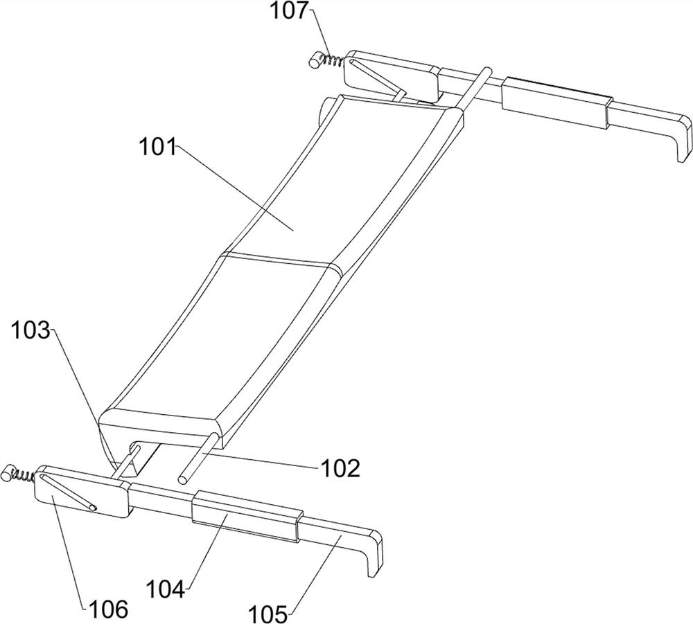
[0037] On the basis of Example 2, as Figure 4-6As shown, it also includes a jacking mechanism 10. The jacking mechanism 10 includes a turning plate 101, a turning rod 102, a connecting column 103, a sliding sleeve 104, an L-shaped sliding rod 105, a chute plate 106 and a spring 107. The seat plate 2 An opening 100 is opened on the seat plate 2, a rotating rod 102 is rotatably connected to the seat plate 2, and a rotating plate 101 is connected to the rotating rod 102. Connecting posts 103 are connected on both sides, sliding sleeves 104 are connected on both front and rear sides of the seat plate 2, and an L-shaped sliding rod 105 is slidably connected in the sliding sleeve 104. The threaded sleeve 91 is matched with the L-shaped sliding rod 105, and the L-shaped sliding A chute plate 106 is connected to the left side of the rod 105, the chute plate 106 is slidingly matched with the connecting column 103, a spring 107 is connected between the chute plate 106 and the seat plat...
PUM
 Abstract
Description
Claims
Application Information
 - R&D
- Intellectual Property
- Life Sciences
- Materials
- Tech Scout
- Unparalleled Data Quality
- Higher Quality Content
- 60% Fewer Hallucinations
Browse by: Latest US Patents, China's latest patents, Technical Efficacy Thesaurus, Application Domain, Technology Topic, Popular Technical Reports.
© 2025 PatSnap. All rights reserved.Legal|Privacy policy|Modern Slavery Act Transparency Statement|Sitemap|About US| Contact US: help@patsnap.com


