Concrete distributing mechanism for concrete pump

A concrete pump and concrete technology, which is applied in the direction of building structure, building material processing, construction, etc., can solve the problems of physical consumption, high labor intensity of personnel, easy contamination of concrete, etc., and achieve the effect of saving energy and manpower

Active Publication Date: 2021-06-25
江西省科森建筑科技有限公司
View PDF7 Cites 0 Cited by
  • Summary
  • Abstract
  • Description
  • Claims
  • Application Information

AI Technical Summary

Problems solved by technology

[0003] During the use of the concrete pump truck, the discharge pipe of the concrete pump truck is placed at the position where the concrete needs to be discharged for discharge work. In the prior art, when the discharge pipe is discharging, it usually requires multiple people to hold the hose or use The rope is fixed for traction to determine the discharge direction of the hose. This method is not only very labor-intensive. The Chinese patent publication number is CN108442707A. Fix the pouring pipe, and then use the wheels to drive the pouring pipe to move, but in the actual work of concrete discharge on the ground, the concrete discharged through the pouring pipe flows freely on the ground, and the horizontal distance between the wheels and the pouring pipe is relatively short. Therefore, it is very easy to be contaminated with concrete, which affects the walking of the wheels, and it is troublesome to clean. In addition, in the prior art, a staff member is required to hold the push plate at the position of the concrete discharge pipe to push away the concrete below the concrete pump discharge pipe. High labor costs and high labor intensity

Method used


Image

  • Concrete distributing mechanism for concrete pump
  • Concrete distributing mechanism for concrete pump
  • Concrete distributing mechanism for concrete pump

Examples


no. 1 example

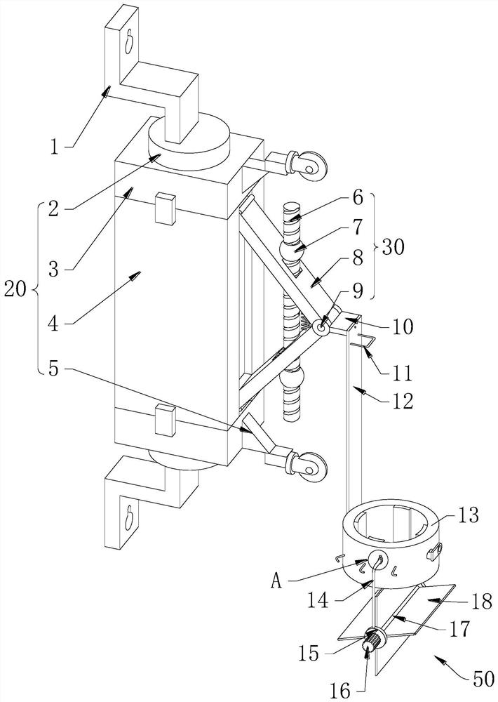
[0024] First example: see Figure 1-Figure 3 , a concrete distributing mechanism for concrete pumps, including a support assembly 20, the upper and lower ends of the support assembly 20 are fixed to the hanging board 1 for hanging on the wall, and the inside of the two hanging boards 1 are provided with gourd holes with a narrow top and a wide bottom , the right end of the support assembly 20 is installed with a length adjustment part 30, and the right end of the length adjustment part 30 is installed with a vertical plate 12, and the lower end of the vertical plate 12 is fixed with a pipe clip 13 for clamping and fixing the discharge pipe of the concrete pump. L-shaped rods 14 are fixed at both ends, and a pusher 50 for pushing concrete is installed at the lower ends of the two L-shaped rods 14 .

[0025] Nails are nailed into the corresponding position on the wall, and then hung on the nails through the gourd holes on the two hanging boards 1, so that the mechanism can be hu...

no. 2 example

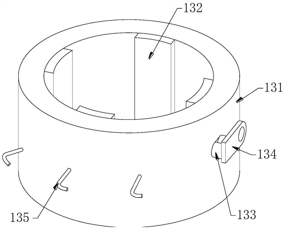
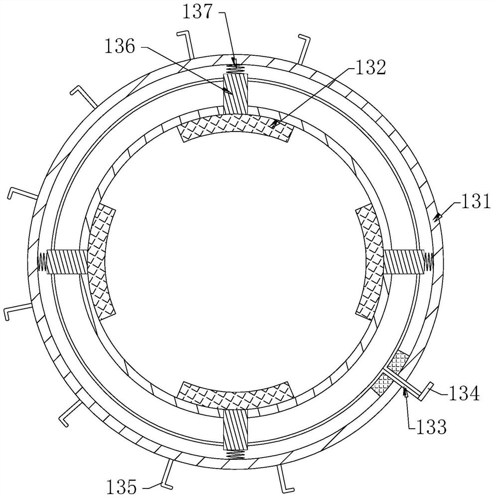
[0031] Second example: see Figure 1-Figure 4 , the annular outer end of the annular housing 131 fixes the ring 141, the L-shaped rod 14 is arranged inside the ring 141 and extends from the ring 141, the upper end of the ring 141 is threaded to install a locking bolt 142, and the locking bolt 142 passes through The upper end of the ring 141 is closely connected with the upper end of the L-shaped rod 14, and the L-shaped rod 14 is locked by the locking bolt 142, so that the pusher 50 is set at the discharge port of the concrete pump discharge pipe, and the pusher 50 needs to be adjusted. position, the locking bolt 142 can be loosened to unlock the L-shaped rod 14, and then the L-shaped rod 14 can be rotated to drive the pusher 50 to rotate until the pusher 50 is moved from the discharge port of the concrete pump discharge pipe. Tighten the locking bolt 142 after leaving, so that the pusher 50 is removed from the discharge port of the concrete pump discharge pipe when the pusher...

Embodiment 1

[0038] Embodiment 1 realizes wall-mounted distribution, which is convenient for concrete distribution on the ground. Embodiment 2 realizes mobile distribution, which is convenient for concrete distribution on the wall, which is suitable for different use scenarios and has good use effect.


PUM


Abstract

The invention relates to the technical field of concrete construction, in particular to a concrete distributing mechanism for a concrete pump, which includes a hanging board, a support assembly, a length adjustment member, a riser, a pipe clamp, an L-shaped rod and a pusher, and is mounted on the wall Nails are nailed into the corresponding position on the top, and then hung on the nails through the gourd holes on the two hanging boards, so that the mechanism can be hung on the wall, without the need for personnel to use pull ropes to pull or hold the discharge pipe by hand, saving energy, through The support assembly, the length adjustment piece and the vertical plate support the pipe clip, use the pipe clip to clamp and lock the concrete pump discharge pipe, use the L-shaped rod to support the push piece, and use the push piece to lock the concrete pump discharge pipe The concrete discharged from the pump is pushed to remove the concrete directly below the discharge pipe of the concrete pump, and there is no need for a special person in the prior art to use the push plate to push the concrete at the position of the discharge port, which saves manpower.

Description

technical field [0001] The invention relates to a concrete distributing mechanism for a concrete pump, which belongs to the technical field of concrete construction. Background technique [0002] There are mainly five control methods of the electrical control system of concrete pump trucks: mechanical, hydraulic, electromechanical, electrical control, programmable controller, and logic circuit control. The control system of the concrete pump truck is mainly used to control the main hydraulic pump. The flow rate and engine speed can be changed to change the concrete discharge volume of the pump truck. If hydraulic control is used, the hydraulic driving force can be directly obtained from the pumping system of the pump truck, and the control can be realized through the manual hydraulic valve. [0003] During the use of the concrete pump truck, the discharge pipe of the concrete pump truck is placed at the position where the concrete needs to be discharged for discharge work. I...

Claims


Application Information

Patent Timeline
Patent Type & Authority Patents(China)
IPC IPC(8): E04G21/04
CPCE04G21/04E04G21/0418E04G21/0427
Inventor 姚超坤
Owner 江西省科森建筑科技有限公司
Why Eureka
Try Eureka