Pneumatic automatic return device

An automatic return and air chamber technology, which is applied to switches with braking devices, door/window accessories, buildings, etc., can solve the problem of uneven door return speed, achieve the best user experience, convenient operation, and wide The effect of application range

Pending Publication Date: 2020-12-15
WEIFANG ZHENGXIN PNEUMATIC TECH CO LTD
View PDF0 Cites 0 Cited by
  • Summary
  • Abstract
  • Description
  • Claims
  • Application Information

AI Technical Summary

Problems solved by technology

[0004] The invention proposes a pneumatic automatic return device, which solves the problem of different return speeds of doors with different weights in the prior art

Method used


Image

  • Pneumatic automatic return device
  • Pneumatic automatic return device
  • Pneumatic automatic return device

Examples


Embodiment 1

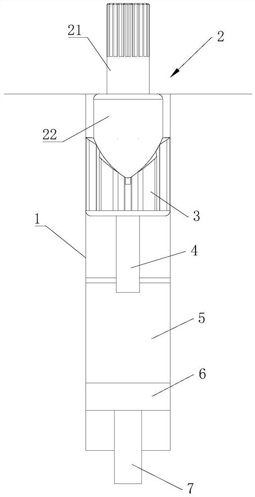
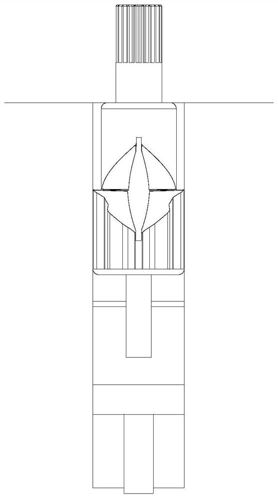
[0035] Such as figure 1 with figure 2 As shown, it is a schematic diagram of two different states of the pneumatic automatic return device of the present invention, and it is a schematic diagram of two extreme states. The pneumatic automatic return device is used to be installed on the door to realize the automatic return of the door. The device When installing, the rotation center of the door is installed on the rotating shaft 21 of the upper protruding shaft 2 in the figure, and the door and the rotating shaft 21 rotate synchronously. figure 1 In the shown state, the door is in a closed state, and when the door and the rotating shaft 21 rotate 90°, it will be in a closed state. figure 2 In the state shown, the door is opened to the maximum extent at this time, and then the door can be opened from figure 2 Automatically return to the position shown in the state figure 1 The state shown realizes the automatic closing of the door, and the structure of this embodiment is d...


PUM


Abstract

The invention provides a pneumatic automatic return device which solves the problem that return speeds of doors with different weights are different in the prior art. The pneumatic automatic return device comprises a gear sleeve, an upper convex shaft, a lower convex shaft, a piston, a closed air chamber and an adjusting rod. The gear sleeve is of a hollow structure; the upper convex shaft is arranged in the gear sleeve, one end of the upper convex shaft extends outwards from the end part of the gear sleeve, and the upper convex shaft only rotates in the gear sleeve; the lower convex shaft isalso arranged in the gear sleeve and does reciprocating rectilinear motion only in the length direction of the gear sleeve, the upper convex shaft and the lower convex shaft are in contact and alwayshave acting force, and the rotating motion of the upper convex shaft is synchronous with the rectilinear motion of the lower convex shaft; one end of the piston is used for continuously propping the lower convex shaft against the upper convex shaft; the other end of the piston extends into the closed air chamber, and the closed air chamber is provided with a movable end face used for adjusting thespace size of the closed air chamber; and the adjusting rod is arranged on the gear sleeve in a matched manner and abuts against the movable end face.

Description

technical field [0001] The invention relates to the technical field of door devices, in particular to a pneumatic automatic return device which is simple in structure, easy to use and capable of adjusting the closing speed according to needs. Background technique [0002] The ground spring is a hydraulic door closer, its basic configuration is the sky shaft and the ground shaft (or called the foot), the sky shaft is an accessory that connects the door frame and the door leaf in the upper part, and is fixed on the door leaf and can be adjusted with bolts. Composed of a bolt-type shaft and a shaft sleeve fixed on the door leaf, the sky shaft and ground shaft can be applied to almost all wooden, steel, aluminum alloy doors and frameless glass doors using glass door clips. [0003] The rotor and shaft in the pneumatic floor spring in the prior art are of split structure. After the door is closed violently or used for a long time, the rotor and shaft of the split structure are pr...

Claims


Application Information

Patent Timeline
Patent Type & Authority Applications(China)
IPC IPC(8): E05F3/02E05F3/20
CPCE05F3/04E05F3/22
Inventor 于宝峰卢波畅
Owner WEIFANG ZHENGXIN PNEUMATIC TECH CO LTD
Why Eureka
Try Eureka