A hospital bed that is convenient for bedridden patients in internal medicine to turn over
A patient and hospital bed technology, applied in the field of hospital beds, can solve problems such as inconvenience for patients to turn over, and achieve the effects of improving safety, enhancing safety, and turning over stably
- Summary
- Abstract
- Description
- Claims
- Application Information
AI Technical Summary
Problems solved by technology
Method used
Image
Examples
Embodiment 1
[0027] A hospital bed that is convenient for bedridden patients in internal medicine to turn over, such as figure 1 , figure 2 , image 3 , Figure 4 As shown, it includes a base 1, a universal wheel 2, a mattress 3, a mechanism switch 4 and an overturning mechanism 5. The bottom of the base 1 is equipped with a universal wheel 2 that is symmetrically rotated on the front and rear sides, and the center of the base 1 is provided with a mattress. 3. A mechanism switch 4 is provided on the right side of the base 1, and a turning mechanism 5 is provided at the bottom of the base 1.
[0028] The patient lies on the mattress 3 and can gently push the base 1. Since the universal wheel 2 is provided, the device can be moved, which is convenient for doctors and nurses to use. When the patient wants to turn over, the mechanism switch 4 can be toggled Make turning mechanism 5 operate, just can realize the purpose of turning over to patient, after turning over, toggle mechanism switch...
Embodiment 2
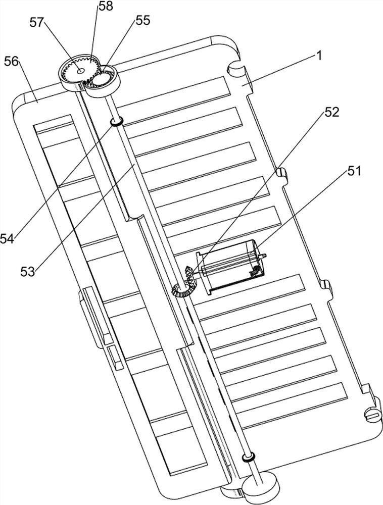
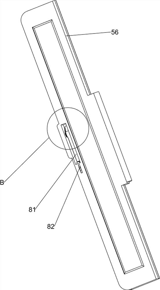
[0030] On the basis of Example 1, such as figure 1 , figure 2 , Figure 4 As shown, the turnover mechanism 5 includes a motor 51, a bevel gear set 52, a first transmission shaft 53, a first full gear 54, a second full gear 55, a flipping plate 56, a rotating shaft 57 and a third full gear 58, and the base 1 A motor 51 is installed on the right side of the bottom, a first transmission shaft 53 is provided in the middle of the bottom of the base 1, and a bevel gear set 52 is arranged between the first transmission shaft 53 and the output shaft of the motor 51, and the front and rear symmetry of the first transmission shaft 53 A first full gear 54 is provided, a second full gear 55 is provided at the tops of the front and rear sides of the first transmission shaft 53, and a rotating shaft 57 is provided on the left side of the base 1 in a symmetrical front and rear rotation, and a turning shaft 57 is provided on the left side of the base 1. Both the plate 56 and the rotating s...
Embodiment 3
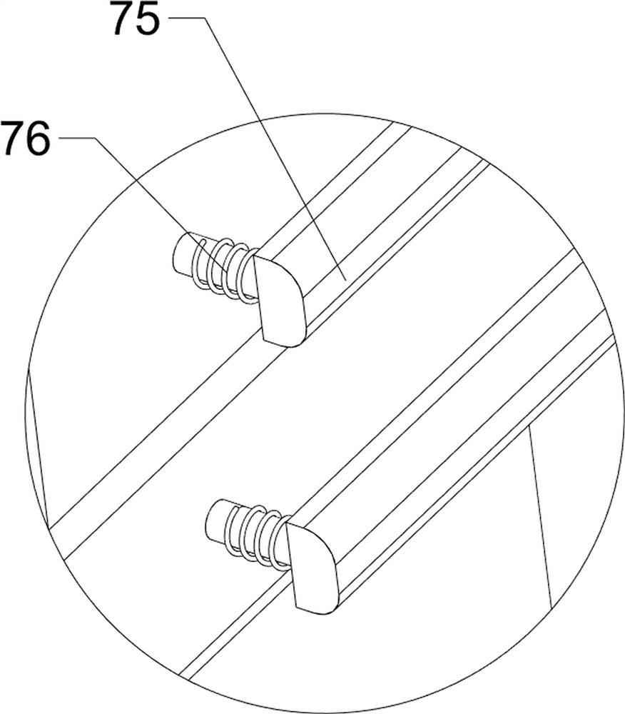
[0033] On the basis of Example 2, such as figure 1 , figure 2 , Figure 5 , Image 6 , Figure 7 , Figure 8 , Figure 9As shown, a stretching mechanism 6 is also included, and the right part of the base 1 is provided with a stretching mechanism 6. The stretching mechanism 6 includes a guardrail 61, a first telescopic rod 62, a first rack 63, a second transmission shaft 64, a first Four full gears 65, the third transmission shaft 66, the fifth full gear 67, the sixth full gear 68, the fourth transmission shaft 69, the seventh full gear 610 and the second rack 611, the right sliding type on the base 1 is provided with Guardrail 61, base 1 right part is provided with the first telescopic rod 62 front and back symmetrically, the top of first telescopic rod 62 is connected with guardrail 61, guardrail 61 is provided with second rack 611 front and back symmetrically on the left side, base 1 bottom left side is symmetrical front and rear The rotary type is provided with a sec...
PUM
 Abstract
Description
Claims
Application Information
 - R&D
- Intellectual Property
- Life Sciences
- Materials
- Tech Scout
- Unparalleled Data Quality
- Higher Quality Content
- 60% Fewer Hallucinations
Browse by: Latest US Patents, China's latest patents, Technical Efficacy Thesaurus, Application Domain, Technology Topic, Popular Technical Reports.
© 2025 PatSnap. All rights reserved.Legal|Privacy policy|Modern Slavery Act Transparency Statement|Sitemap|About US| Contact US: help@patsnap.com


