A machine tool faceplate-type centering device for a tooling fixture and a centering method thereof

A technology of tooling fixtures and centering devices, which is applied to positioning devices, manufacturing tools, metal processing machinery parts, etc., can solve the problem that it cannot be accurately placed at a position that roughly coincides with the center of the machine tool, sometimes with a difference of tens of millimeters. Reduce the accuracy of the table spindle, scratches on the machine table, etc., to save manpower, improve alignment efficiency, and improve efficiency

Active Publication Date: 2022-07-12
AECC AERO SCI & TECH CO LTD
View PDF19 Cites 0 Cited by
  • Summary
  • Abstract
  • Description
  • Claims
  • Application Information

AI Technical Summary

Problems solved by technology

However, in the process of centering, some problems were encountered. For example, the faceplate of the machine tool is a flat workbench, and the bottom plate of the fixture is also a plane. The coincidence position sometimes differs by dozens of millimeters. Fortunately, it can be placed within a few millimeters. If it is a major fixture placed, these errors will cause a lot of friction after the fixture contacts the workbench plane. It is time-consuming and labor-intensive to move the fixture. The master worker uses iron rods to knock it out, and levers to pry it. After a long time, the machine tool workbench is severely scratched, and the fixture alignment belt will also be knocked. Injury, the spindle of the worktable will also be affected by the impact force of the alignment, resulting in a decrease in accuracy

Method used


Image

  • A machine tool faceplate-type centering device for a tooling fixture and a centering method thereof
  • A machine tool faceplate-type centering device for a tooling fixture and a centering method thereof
  • A machine tool faceplate-type centering device for a tooling fixture and a centering method thereof

Examples


Embodiment 1

[0038] see Figure 1-5 , the present invention provides a kind of technical scheme:

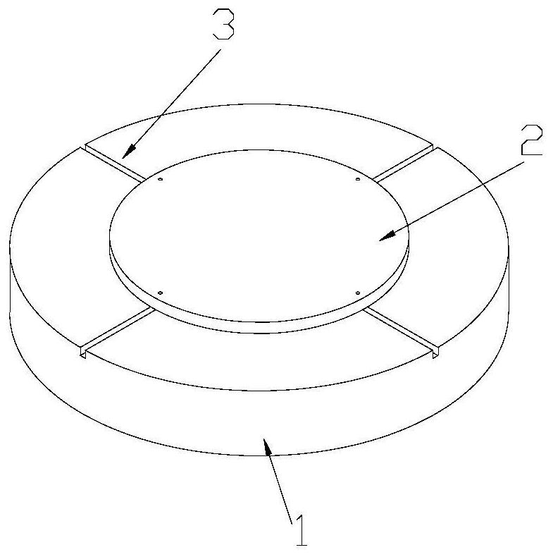
[0039] Please refer to Figure 1-4 , a centering device of the machine tool faceplate 1 type of a tooling fixture 2, comprising:

[0040] Machine tool faceplate 1;

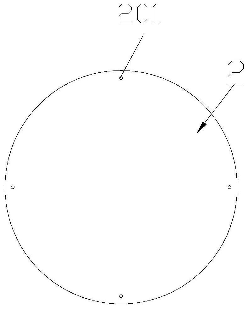
[0041] The tooling fixture 2 carried on the machine tool faceplate 1 and a number of positioning grooves 3 opened on the machine tool faceplate 1, and a number of the positioning grooves 3 are evenly arranged along the center of the machine tool faceplate 1; And,

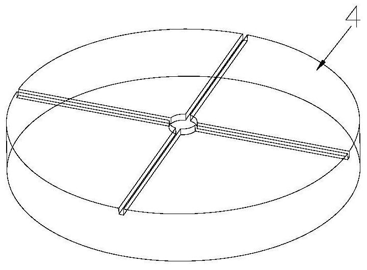
[0042] Several positioning blocks 4 are installed on the fixture 2 , one end of the positioning blocks 4 is threadedly connected with the fixture 2 , and the other end of the positioning blocks 4 is installed in sliding fit with the positioning groove 3 .

[0043] One end of the positioning block 4 of the present invention is installed on the fixture 2, and one end of the positioning block 4 can be slidably installed in the positioning groove 3 of the machine tool f...


PUM


Abstract

The invention discloses a machine tool faceplate-type centering device of a tooling fixture and a centering method thereof, comprising: a machine tool faceplate; a tooling fixture carried on the machine tool faceplate and a plurality of positioning grooves opened on the machine tool faceplate, Several positioning grooves are evenly arranged along the center of the machine tool faceplate; and several positioning blocks are installed on the fixture, one end of the positioning blocks is screwed with the fixture, and the other end of the positioning blocks Installed in sliding fit with the positioning groove. The principle that the cross centers of the two objects overlap each other in the present invention enables the faceplate of the machine tool and the tooling fixture to be quickly and accurately aligned, and the centering error is greatly reduced.

Description

technical field [0001] The invention relates to the technical field of positioning tooling, in particular to a machine tool faceplate-type centering device of a tooling fixture and a centering method thereof. Background technique [0002] At present, there are many fixtures for rotary casing parts in aviation units, which are composed of a circular bottom plate and functional parts on the bottom plate. These fixtures are indispensable in the manufacturing process of parts. [0003] After the workers use the crane hoisting fixture on the machine tool, a very important job is to align the fixture so that the center of the fixture coincides with the center of rotation of the machine tool faceplate. However, in the process of centering, we encountered some problems, such as: the faceplate of the machine tool is a flat worktable, and the bottom plate of the fixture is also a flat surface. The overlapping position is sometimes a few tens of millimeters away. If you are lucky, it ...

Claims


Application Information

Patent Timeline
Patent Type & Authority Patents(China)
IPC IPC(8): B23Q3/00
CPCB23Q3/00Y02P70/10
Inventor 李福光曾浩李雪梅谭小波陈海筠
Owner AECC AERO SCI & TECH CO LTD
Why Eureka
Try Eureka