
Unmanned aerial vehicle flight control system and ducted fan installation and fly-by-wire interface module

A flight control system, unmanned aerial vehicle technology, applied in aircraft control, aircraft transmission, aircraft power transmission and other directions, can solve the problems of unmanned aircraft transportation, inconvenience in launching, installation obstacles, etc.

Active Publication Date: 2020-12-18
成都云鼎智控科技有限公司
View PDF6 Cites 0 Cited by
  • Summary
  • Abstract
  • Description
  • Claims
  • Application Information

AI Technical Summary

Problems solved by technology

At present, for UAVs that are long in shape and usually fly along their own length direction, the propulsion system and rudder system are usually set far apart in the length direction of UAVs, which is easy for UAVs. The installation of other functional components creates obstacles, and it also brings inconvenience to the transportation and launch of UAVs

Method used


Image

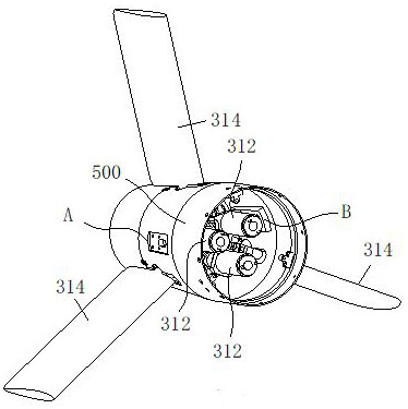
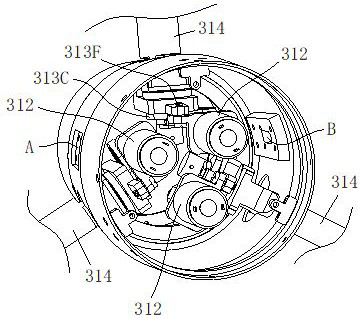
  • Unmanned aerial vehicle flight control system and ducted fan installation and fly-by-wire interface module
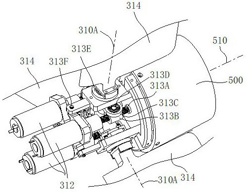
  • Unmanned aerial vehicle flight control system and ducted fan installation and fly-by-wire interface module
  • Unmanned aerial vehicle flight control system and ducted fan installation and fly-by-wire interface module

Examples


Embodiment Construction

[0020]The present invention will be clearly and completely described below in conjunction with the accompanying drawings. Those skilled in the art will be able to implement the present invention based on these descriptions. Before the present invention is described in conjunction with the accompanying drawings, it should be pointed out that:

[0021] The technical solutions and technical features provided in each part of the present invention, including the following description, can be combined with each other under the condition of no conflict.

[0022] In addition, the embodiments of the present invention involved in the following descriptions are usually only a part of the embodiments of the present invention rather than all the embodiments. Therefore, based on the embodiments of the present invention, those skilled in the art will not make any All other embodiments obtained under the premise of creative labor shall belong to the protection scope of the present invention....


PUM


Abstract

The invention discloses an unmanned aerial vehicle flight control system and a ducted fan installation and fly-by-wire interface module. The unmanned aerial vehicle flight control system comprises a master control system, a propulsion system, a rudder system and a feedback system. The propulsion system comprises at least two ducted fan propulsion units in total, and the rudder system comprises atleast three steering engines in total. The propulsion system further comprises the ducted fan installation and fly-by-wire interface module. The module comprises ducted fan installation and fly-by-wire interface butt joint devices which are used for installing corresponding ducted fans on the outer side wall of the tail of an unmanned aerial vehicle and enabling fan-side fly-by-wire interfaces onthe ducted fans to be in butt joint with corresponding control-side fly-by-wire interfaces arranged on the outer side wall of the tail of the unmanned aerial vehicle in a protruding manner, grooves for accommodating the corresponding control-side fly-by-wire interfaces in a matched manner are formed in supports of the devices, and in the ducted fan installation and fly-by-wire interface butt jointdevices, the insertion ends of the corresponding fan-side fly-by-wire interfaces enter the grooves.

Description

technical field [0001] The invention relates to a flight control system of an unmanned aerial vehicle, which mainly includes a main control system, a propulsion system, a rudder system and a feedback system. Background technique [0002] The flight control system of UAV usually includes main control system, propulsion system, rudder system and feedback system. Among them, the propulsion system is used to provide thrust to keep the UAV flying; the rudder system is used to realize the steering of the UAV; the main control system is used to control the operation of the propulsion system and the rudder system; the feedback system is used to feed back to the main control system Control results for unmanned aerial vehicles. The UAV flight control system needs to match the type of UAV. At present, for UAVs that are long in shape and usually fly along their own length direction, the propulsion system and rudder system are usually set far apart in the length direction of UAVs, whic...

Claims


Application Information

Patent Timeline
Patent Type & Authority Applications(China)
IPC IPC(8): B64C19/00B64C13/50
CPCB64C13/50B64C19/00
Inventor 唐冰刘以建
Owner 成都云鼎智控科技有限公司
Learn More