Fracturing method for subterranean reservoirs

a reservoir and subterranean technology, applied in the field of subterranean reservoirs, can solve the problems of fracture, formation to break down, etc., and achieve the effect of preventing further growth of fractures

Active Publication Date: 2010-01-12
SCHLUMBERGER TECH CORP
View PDF21 Cites 38 Cited by
  • Summary
  • Abstract
  • Description
  • Claims
  • Application Information

AI Technical Summary

Benefits of technology

[0014]The proppant is preferably used to block fluid transport at the entrance of the fracture. This near wellbore s

Problems solved by technology

Sufficient pressure is applied to the acidizing fluid to cause the formation

Method used


Image

  • Fracturing method for subterranean reservoirs
  • Fracturing method for subterranean reservoirs
  • Fracturing method for subterranean reservoirs

Examples


Embodiment Construction

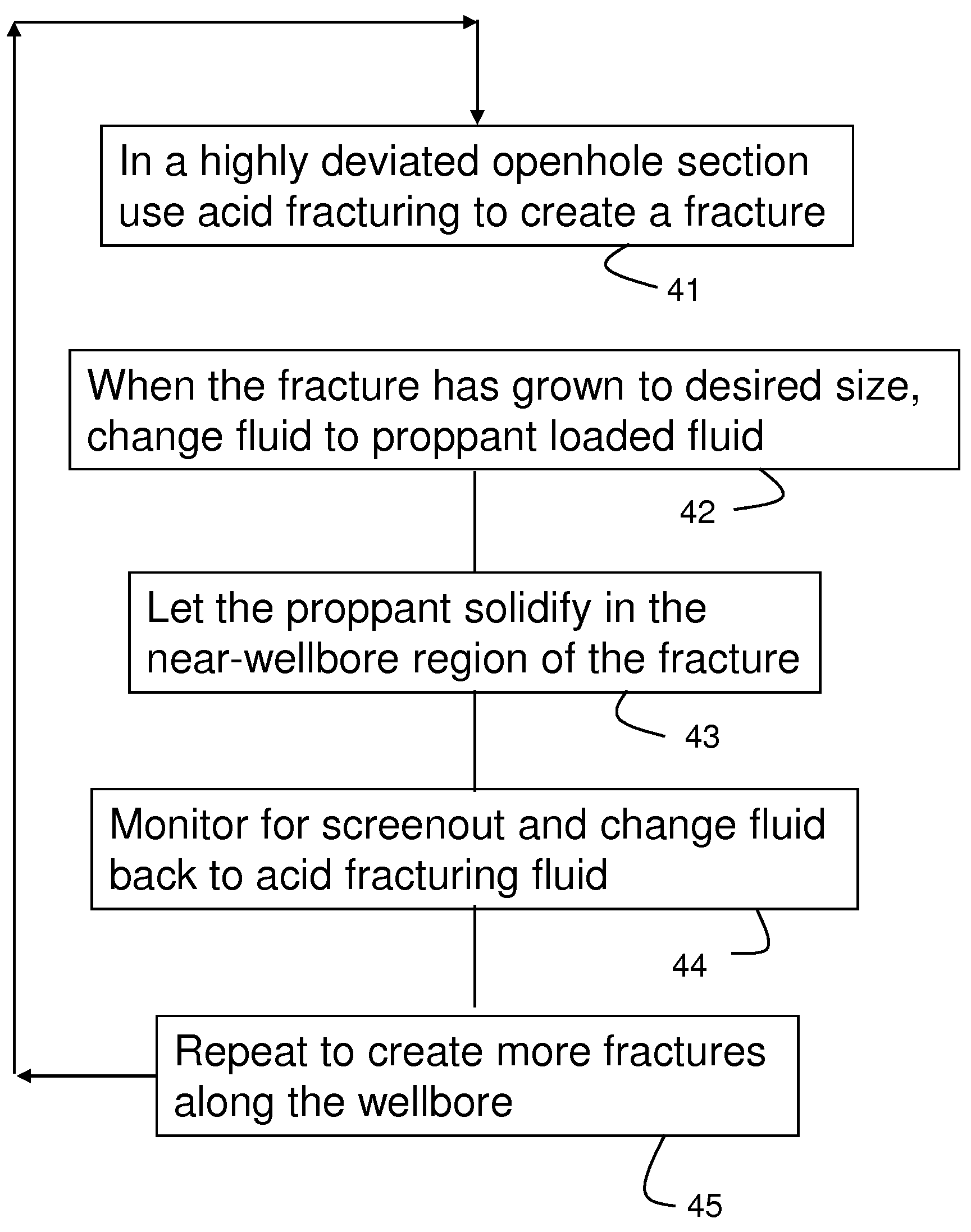
[0027]In the following, two examples of the present invention are described in greater detail. The first example includes the following steps and variants described while referring to the drawings as listed above.

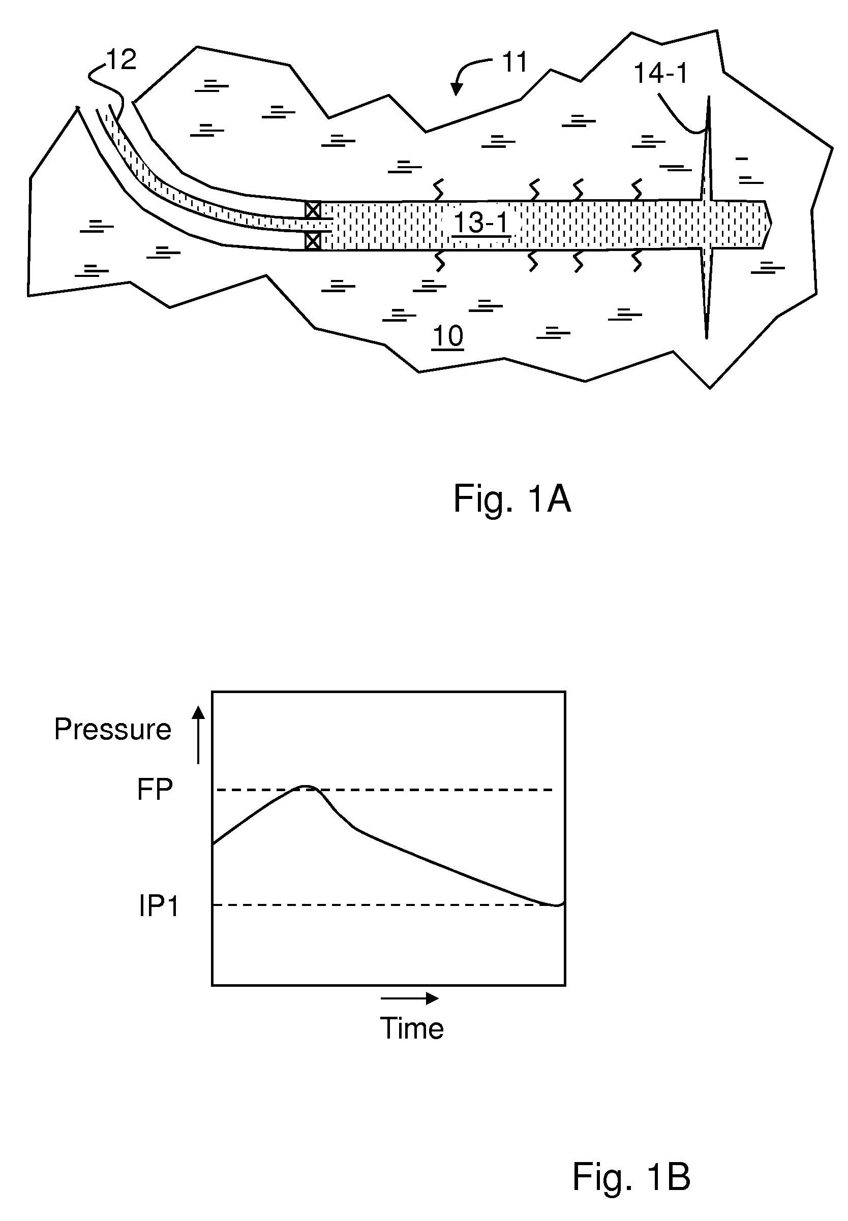
[0028]In FIG. 1A, there is shown a single horizontal section 11 of a well in a formation 10 of carbonate rock. The section is completed as open hole with a pipe 12 providing a hydraulic connection to the surface equipment (not shown) including pumps and mixers as in a standard fracturing operation. At the stage of the operation shown in FIG. 1A, the section 11 is filled with an acid fracturing fluid 13-1 in direct contact with the wall of the formation 10. The treatment starts by pressurizing the acid fluid 13-1 at high pressure above the formation fracturing pressure FP (as shown in FIG. 1B) to create an acid fracture 14-1 at the location with the lowest in-situ stress or the weakest point along the well section 11.

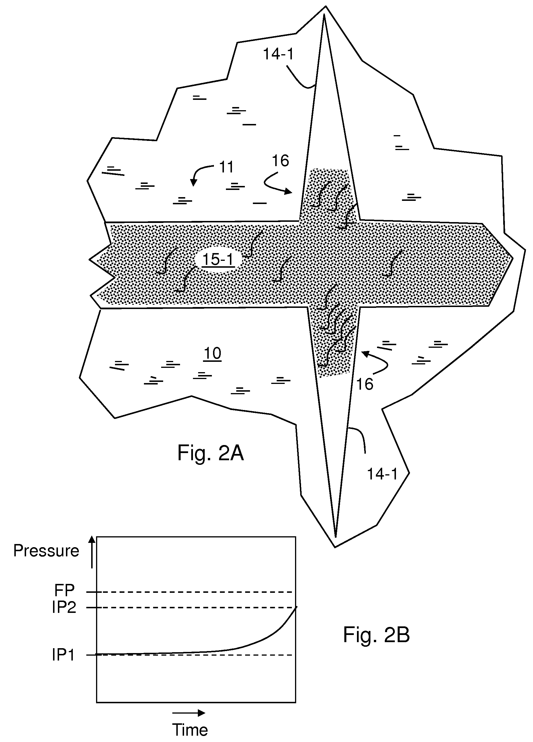
[0029]Initially, more than one fracture may be created sim...


PUM


Abstract

A method of creating multiple fractures in a well traversing a formation is described using pressurized fluids in a highly deviated or horizontal section of the well at a pressure above the fracturing pressure of the formation, wherein for creating a fracture the pressurized fluid is alternated between an acid fracturing fluid and a proppant loaded fluid, such that the proppant blocks the flow of pressurized fluid into a fracture created during a previous step of the method and the subsequently pressurized acid fracturing fluid creates a new fracture at a location along the highly deviated or horizontal section different from the location of the previously created fracture.

Description

FIELD OF THE INVENTION[0001]The invention relates to subterranean reservoirs, particularly hydrocarbon reservoirs. More specifically, the invention pertains to methods of fracturing wells drilled as horizontal or highly deviated open holes into subterranean reservoirs, particularly carbonate reservoirs.BACKGROUND[0002]Hydrocarbons (oil, natural gas, etc.) are typically obtained from a subterranean geologic formation (i.e., a “reservoir”) by drilling a well that penetrates the hydrocarbon-bearing formation. A typical well is drilled as a vertical well into the subsurface. However, in recent times drilling practice evolved to include drilling of highly deviated (from the vertical) or horizontal wells to improve the contact of the well with a specific formation layer or pay zone.[0003]Prior to production, the well is completed with the installation of production facilities, such as casing, production pipes and pumps. The hydrocarbon industry distinguishes between two basic types of com...

Claims


Application Information

Patent Timeline
IPC IPC(8): E21B43/267
CPCE21B43/267
Inventor GU, HONGRENBROWN, J. ERNESTCHANG, FAKUEN F.
Owner SCHLUMBERGER TECH CORP
Why Eureka
Try Eureka