Working platform for engineering quality management

A working platform, engineering quality technology, applied in the direction of measuring devices, adopting mechanical devices, mechanical measuring devices, etc., can solve problems such as trouble, loss of building materials, and heavy

Active Publication Date: 2020-12-18
浙江林鸥工程管理有限公司
View PDF13 Cites 0 Cited by
  • Summary
  • Abstract
  • Description
  • Claims
  • Application Information

AI Technical Summary

Problems solved by technology

[0002] Steel bars in the construction field are frequently used building materials. Traditional building steel bars are usually made into steel cages. The steel cages are generally hollow and long tubes. The inner diameter of the steel cages has different detection methods. Weld the steel bars together, place the intersection point in the center of the steel cage, and then use a tape measure to measure the length of both ends of the steel bars on the circumference of the steel cage. When the hole diameter of the steel cage is large, this is a relatively stupid method, and it is difficult to align the center of the circle. It is heavy and cumbersome to move the welded long steel bar to measure the hole diameter, and the measurement error is also large. In order to improve the accuracy and measurement efficiency of the steel cage hole diameter detection, it is necessary to improve the design
[0003] In addition, at present, during the working process of construction units, excessive loss of building materials often occurs, and when resting at night, building materials may also cause waste of raw materials due to theft or external pollution. Monitoring and supervision of the body, but there is no such setting at present, and it needs to be improved
[0004] And currently there is no work platform for engineering quality management that can solve the above two problems at the same time, so the present invention provides a work platform that can solve the above problems

Method used


Image

  • Working platform for engineering quality management
  • Working platform for engineering quality management
  • Working platform for engineering quality management

Examples


Embodiment Construction

[0038] The present invention will be further described with reference to the accompanying drawings.

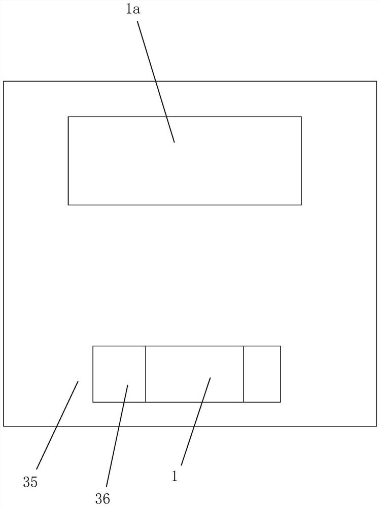
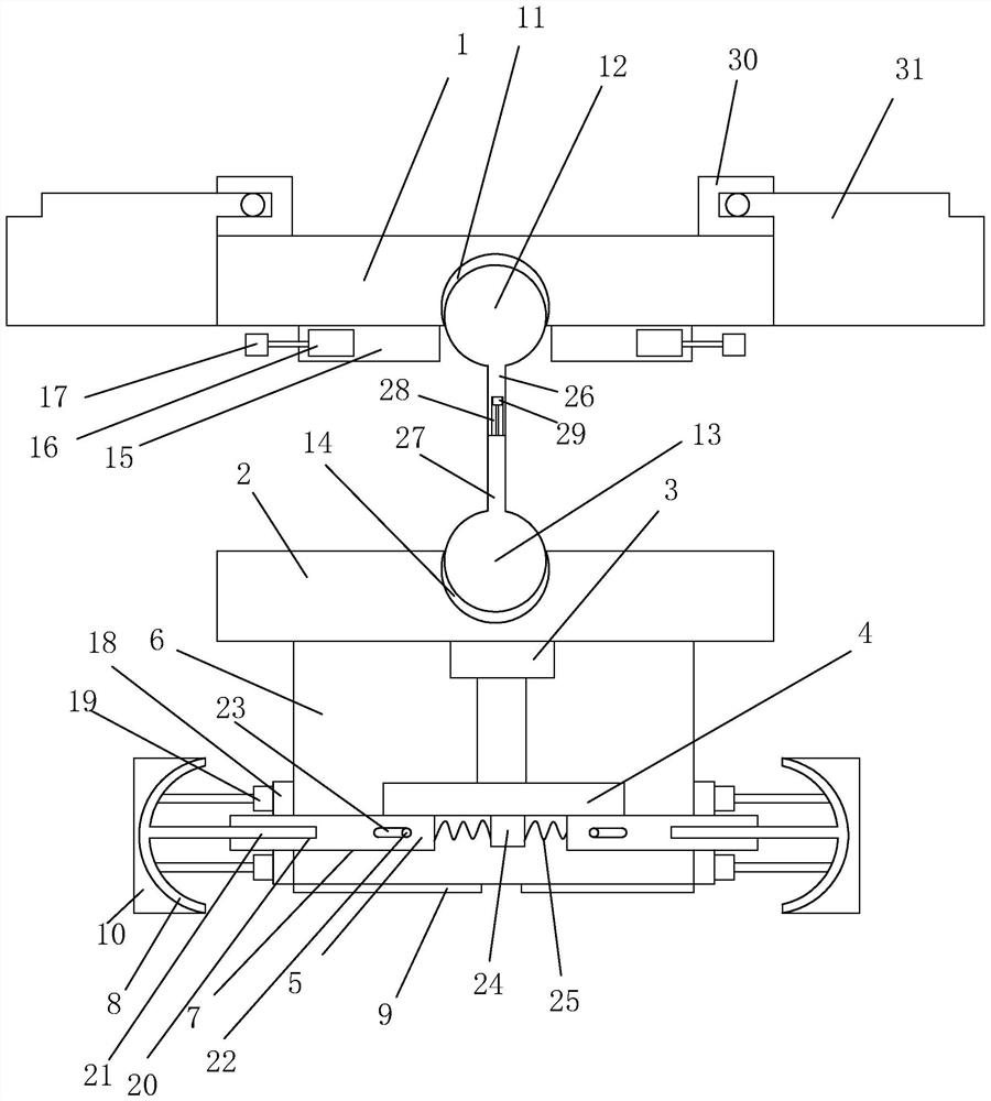
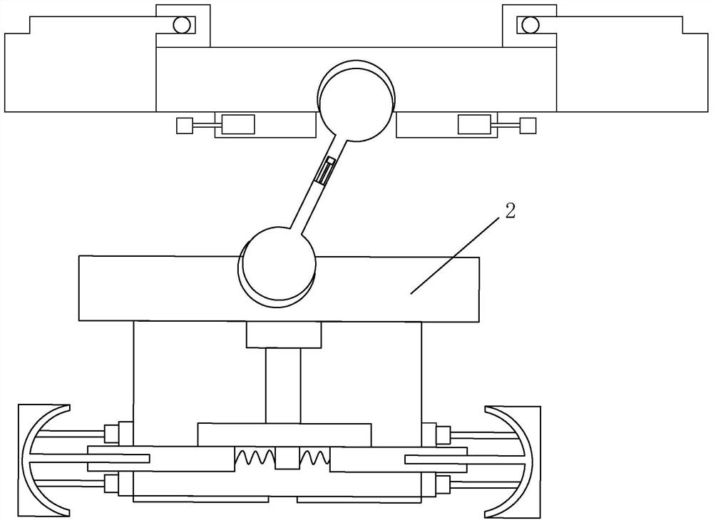
[0039] A working platform for engineering quality management, such as Figure 1-9 As shown, the platform body 35 is included, the platform body 35 is provided with a box body 1a, the top of the box body 1a is provided with a slot 2a communicating with the box body 1a, and the bottom of the slot 2a is provided with a The sub-groove 3a connected to the slot 2a, the inside of the box body 1a is provided with a fixed motor 4a below the slot 2a, the output shaft of the fixed motor 4a is connected with a connecting rod 5a perpendicular to the output shaft, and the connecting rod 5a is away from One end of the fixed motor 4a is provided with a placement block 6a, and the placement block 6a is provided with an accommodation groove 7a, the opening of the accommodation groove 7a faces the sub-groove 3a, and the bottom of the box body 1a is provided with an outlet 8a, and the opening of ...


PUM


Abstract

The invention relates to a working platform for engineering quality management, which comprises a box body, an open groove, a branch groove, a fixed motor, a connecting rod, a placing block, an accommodating groove, an outlet, a closed cylinder, a closed plate and a first positioning plate, a second positioning plate is connected below the first positioning plate, and a rotating motor is arrangedon one side of the second positioning plate; the rotating motor is connected with a driving disc, one side of the driving disc is integrally connected with threaded stripes, three driving blocks matched with the threaded stripes are arranged on one side of the driving disc and are symmetrically distributed relative to the center of the driving disc, and the second positioning plate is connected with a third positioning plate arranged on the outer side of the driving disc in a sleeving mode. And the third positioning plate is provided with a driving groove used for driving the driving block tomove, the side, located outside the driving disc, of the driving block is connected with an arc-shaped plate, and the third positioning plate is provided with scales at an opening of the driving groove. The platform has the advantages of detecting the aperture of the reinforcement cage and monitoring building materials in the box body.

Description

technical field [0001] The invention relates to the technical field of work platforms, in particular to a work platform used for project quality management. Background technique [0002] Steel bars in the construction field are frequently used building materials. Traditional building steel bars are usually made into steel cages. The steel cages are generally hollow and long tubes. The inner diameter of the steel cages has different detection methods. Weld the steel bars together, place the intersection point in the center of the steel cage, and then use a tape measure to measure the length of both ends of the steel bars on the circumference of the steel cage. When the hole diameter of the steel cage is large, this is a relatively stupid method, and it is difficult to align the center of the circle. It is heavy and cumbersome to move the welded long steel bar to measure the hole diameter, and the measurement error is also large. In order to improve the accuracy and measuremen...

Claims


Application Information

Patent Timeline
IPC IPC(8): G01B5/12G01B5/02
CPCG01B5/12G01B5/02
Inventor 胡友军陈小玲胡晗纪强黄和珑范家勇陈骞
Owner 浙江林鸥工程管理有限公司
Why Eureka
Try Eureka