
A Seismic Refraction Wave Traveltime Inversion Method for Co-planar Elements and Co-azimuth Gathers

A technology of angle gathers and retroreflection waves, which is applied in the field of seismic exploration traveltime inversion and can solve problems such as inapplicability

Active Publication Date: 2021-08-20
OCEAN UNIV OF CHINA
View PDF4 Cites 0 Cited by
  • Summary
  • Abstract
  • Description
  • Claims
  • Application Information

AI Technical Summary

Problems solved by technology

[0005] Aiming at the above-mentioned defects existing in the prior art, the present invention proposes a seismic return wave traveltime inversion method of co-planar elements and co-azimuth gathers, which solves the problem that the existing return-wave traveltime velocity modeling method is not suitable for severe surface fluctuations Problems in areas with complex near-surface conditions

Method used


Image

  • A Seismic Refraction Wave Traveltime Inversion Method for Co-planar Elements and Co-azimuth Gathers
  • A Seismic Refraction Wave Traveltime Inversion Method for Co-planar Elements and Co-azimuth Gathers
  • A Seismic Refraction Wave Traveltime Inversion Method for Co-planar Elements and Co-azimuth Gathers

Examples


Embodiment 1

[0060] The present invention is explained and illustrated below in combination with specific embodiments.

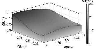
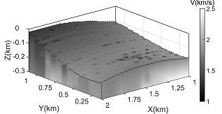
[0061] In order to further illustrate the realization idea and implementation process of this method and prove the effectiveness of the method, a 3D theoretical model of surface undulation and lateral velocity variation is used for testing, and the inversion of the velocity modeling method based on the assumption of a horizontal surface assuming the return wave traveltime equation The results are compared:

[0062] S1: The size of the theoretical velocity model of the present invention is 3000m×1250m×600m, the surface of the theoretical model is undulating and the velocity changes laterally, and the maximum elevation difference is 244m;

[0063] S2: 390 shot points and 2023 receiver points are deployed on the surface; the shot spacing is 75m, the track spacing is 25m, the shot line spacing is 125m, and the receiving point line spacing is 75m;

[0064] S3: Solve the seco...


PUM


Abstract

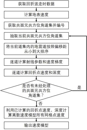
The invention relates to a three-dimensional fluctuating surface velocity modeling method based on co-planar element co-azimuth gather seismic return wave travel time inversion, and belongs to the technical field of seismic exploration travel time inversion. The present invention comprises the following steps: obtaining back-bend wave travel time data; calculating ground surface velocity; obtaining co-planar and co-azimuth gathers and numbering them; extracting the current co-planar and co-azimuth gathers; To the big sort; calculate the return wave ray parameters and velocity gradient track by track; calculate the return point velocity and depth track by track; judge whether there are unprocessed co-planar element co-azimuth gathers, and if so, set the next gather as The current co-planar and co-azimuth gathers are processed, if not, use all the calculated inflection point velocities and depths to calculate the velocities of all grid points in the discrete model; output the velocity model. The invention solves the problem that the existing reverse wave travel time inversion method is not suitable for areas with complex near-surface conditions.

Description

technical field [0001] The invention relates to a three-dimensional fluctuating surface velocity modeling method based on co-planar element co-azimuth gather seismic return wave travel time inversion, and belongs to the technical field of seismic exploration travel time inversion. Background technique [0002] Seismic exploration travel time inversion technology uses seismic wave travel time to establish the velocity model of underground medium. Generally, it can be divided into the first arrival travel time inversion method using the seismic first arrival travel time and the reflected wave travel time inversion method using the seismic reflection travel time. Compared with reflected waves, the first arrival travel time of first arrival waves is often easier to identify and pick up, which makes the application range of first arrival travel time inversion wider. [0003] Conventional first arrival travel time inversion obtains the final inversion result by minimizing the res...

Claims


Application Information

Patent Timeline
Patent Type & Authority Patents(China)
IPC IPC(8): G01V1/30
CPCG01V1/303G01V2210/6222
Inventor 张建中何万利杨华臣
Owner OCEAN UNIV OF CHINA
Learn More