Optical imaging system, image capturing module, electronic device and automobile
An optical imaging system and module technology, which is applied in optics, optical components, instruments, etc., can solve problems such as low resolution, driving risk, and small depth of field, so as to deepen the imaging depth range, widen the imaging field of view, The effect of increasing the field of view range
- Summary
- Abstract
- Description
- Claims
- Application Information
AI Technical Summary
Problems solved by technology
Method used
Image

Examples
no. 1 example
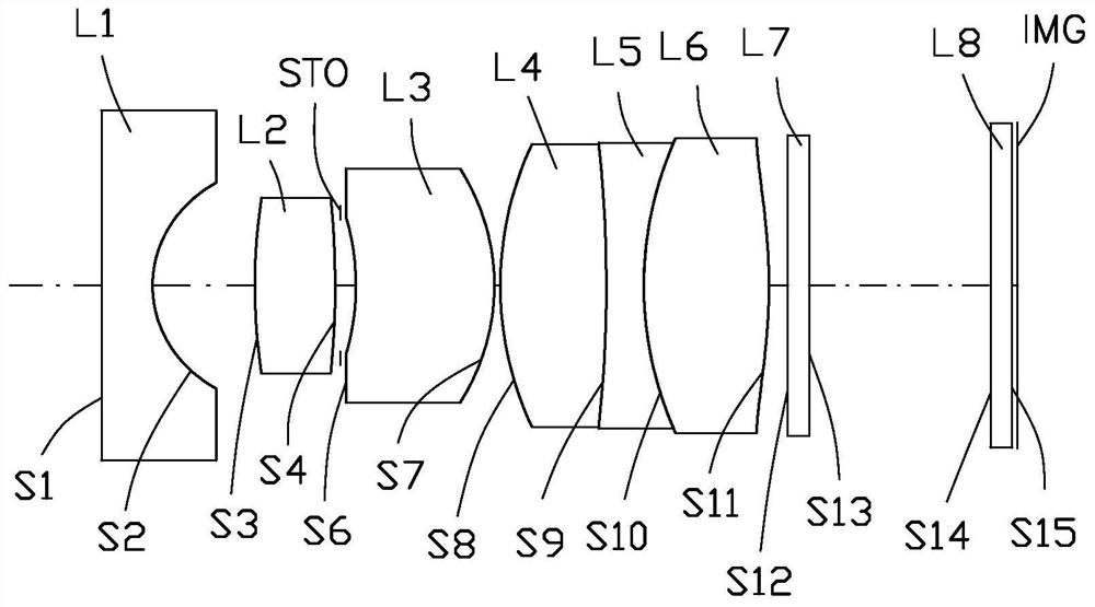
[0149]See alsofigure 1 withfigure 2 , The optical imaging system 10 of the first embodiment sequentially includes from the object side to the image side: a first lens L1 with a negative tortuosity, a second lens L2 with a positive tortuosity, a stop STO, and a third lens with a positive tortuosity. Lens L3, fourth lens L4 with positive refractive power, fifth lens L5 with negative refractive power, sixth lens L6 with positive refractive power, filter L7, and protective glass L8.
[0150]The object side S1 of the first lens L1 is a flat surface, and the image side S2 is a concave surface; the object side S3 of the second lens L2 is a convex surface, and the image side S4 is a convex surface; the object side S6 of the third lens L3 is a concave surface, and the image side S7 is a convex surface The object side surface S8 of the fourth lens L4 is convex, and the image side surface is convex; the object side surface S9 of the fifth lens L5 is concave surface, and the image side surface is ...
no. 2 example
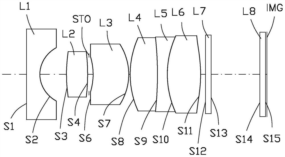
[0162]See alsoimage 3 withFigure 4 , The optical imaging system 10 of the second embodiment includes in order from the object side to the image side: a first lens L1 with a negative tortuous power, a second lens L2 with a positive tortuous power, a stop STO, and a third lens with a positive tortuous power. Lens L3, fourth lens L4 with positive refractive power, fifth lens L5 with negative refractive power, sixth lens L6 with positive refractive power, filter L7, and protective glass L8.
[0163]The object side S1 of the first lens L1 is a flat surface, and the image side S2 is a concave surface; the object side S3 of the second lens L2 is a convex surface, and the image side S4 is a convex surface; the object side S6 of the third lens L3 is a concave surface, and the image side S7 is a convex surface The object side surface S8 of the fourth lens L4 is convex, and the image side surface is convex; the object side surface S9 of the fifth lens L5 is concave surface, and the image side sur...
no. 3 example
[0172]See alsoFigure 5 withFigure 6 , The optical imaging system 10 of the third embodiment sequentially includes from the object side to the image side: a first lens L1 with a negative tortuosity, a second lens L2 with a positive tortuosity, a stop STO, and a third lens with a positive tortuosity. Lens L3, fourth lens L4 with positive refractive power, fifth lens L5 with negative refractive power, sixth lens L6 with positive refractive power, filter L7 and protective glass L8.
[0173]The object side S1 of the first lens L1 is a flat surface, and the image side S2 is a concave surface; the object side S3 of the second lens L2 is a convex surface, and the image side S4 is a convex surface; the object side S6 of the third lens L3 is a concave surface, and the image side S7 is a convex surface The object side surface S8 of the fourth lens L4 is convex, and the image side surface is convex; the object side surface S9 of the fifth lens L5 is concave surface, and the image side surface is c...
PUM
 Abstract
Description
Claims
Application Information
 - R&D
- Intellectual Property
- Life Sciences
- Materials
- Tech Scout
- Unparalleled Data Quality
- Higher Quality Content
- 60% Fewer Hallucinations
Browse by: Latest US Patents, China's latest patents, Technical Efficacy Thesaurus, Application Domain, Technology Topic, Popular Technical Reports.
© 2025 PatSnap. All rights reserved.Legal|Privacy policy|Modern Slavery Act Transparency Statement|Sitemap|About US| Contact US: help@patsnap.com