Optical display system based on Fresnel lens

A Fresnel lens and optical display technology, which is applied in the field of optical display systems based on Fresnel lenses, can solve the problems of large size, light leakage, and heavy weight, and achieve the effects of small size, privacy protection, and light weight

Pending Publication Date: 2022-07-01
江苏鸿蚁光电科技有限公司
View PDF0 Cites 0 Cited by
  • Summary
  • Abstract
  • Description
  • Claims
  • Application Information

AI Technical Summary

Problems solved by technology

However, the current products still have problems such as light leakage, heavy weight, and large volume.

Method used


Image

  • Optical display system based on Fresnel lens
  • Optical display system based on Fresnel lens
  • Optical display system based on Fresnel lens

Examples


Embodiment 1

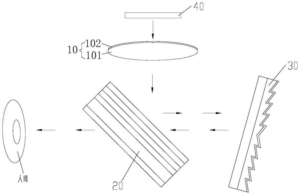
[0038] refer to figure 1 As shown, Embodiment 1 of the present invention provides an optical display system based on a Fresnel lens, including a display 40 , a first optical lens 10 , a second optical lens 20 and a Fresnel lens 30 .

[0039] The display 40 mainly plays the role of emitting light, the display 40 can display 2D or 3D images or videos, and the display 40 can use an OLED display, an LCD display, an LCOS display, a micro-LED display, a mini-LED display or a DLP display, etc.

[0040] The first optical lens 10 is disposed on the light exit light path of the display 40 , and the light emitted by the display 40 is processed by the first optical lens 10 and then transmitted out to form transmitted light.

[0041] The first optical lens 10 includes a first lens 101 and a circular polarizer 102. The circular polarizer 102 is disposed on the side of the first lens 101 close to the display 40. Of course, in another embodiment, the circular polarizer 102 can also be It is ...

Embodiment 2

[0060] refer to Figure 8 As shown, the second embodiment of the present invention provides an optical display system based on a Fresnel lens, including a display 40 , a first optical lens 10 , a second optical lens 20 and a Fresnel lens 30 .

[0061] The display 40 mainly plays the role of emitting light, the display 40 can display 2D or 3D images or videos, and the display 40 can use an OLED display, an LCD display, an LCOS display, a micro-LED display, a mini-LED display or a DLP display, etc.

[0062] The first optical lens 10 is disposed on the light exit light path of the display 40 , and the light emitted by the display 40 is processed by the first optical lens 10 and then transmitted out to form transmitted light.

[0063] In this embodiment, the first optical lens 10 is a transmission mirror.

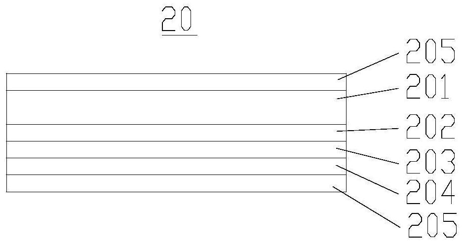
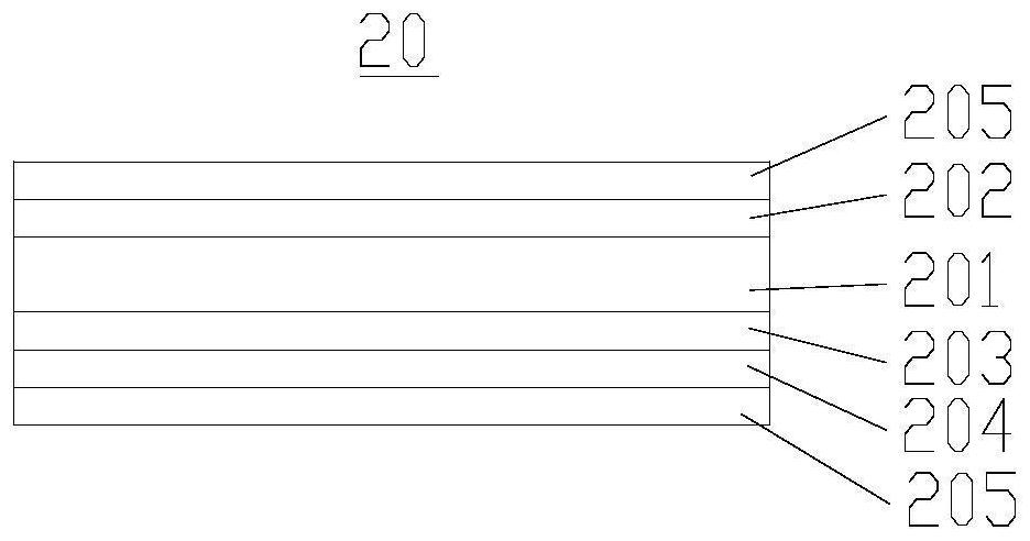
[0064] The second optical lens 20 is disposed on the optical path of the transmitted light of the first optical lens 10 , and the transmitted light transmitted from the first ...

Embodiment 3

[0080] refer to Figure 13 As shown, the second embodiment of the present invention provides an optical display system based on a Fresnel lens, including a display 40 , a first optical lens 10 , a second optical lens 20 and a Fresnel lens 30 .

[0081] The difference between this embodiment and the second embodiment lies in the Fresnel lens 30 .

[0082] The display 40 , the first optical lens 10 and the second optical lens 20 in this embodiment adopt the display 40 , the first optical lens 10 and the second optical lens 20 in the second embodiment, and the structure, working principle and technical effect produced are referred to The corresponding content in the second embodiment will not be repeated here.

[0083] In this embodiment, refer to Figure 14 As shown, the Fresnel lens 30 includes a Fresnel substrate 301 , a transflective film 303 , a filling layer 305 , a third quarter-wave plate layer 304 and a third anti-reflection film 302 .

[0084] The Fresnel surface of th...


PUM


Abstract

The invention provides an optical display system based on a Fresnel lens, and belongs to the technical field of optical imaging, the optical display system comprises a display, a first optical lens, a second optical lens and the Fresnel lens, the first optical lens is arranged on a light emitting path of the display, and the second optical lens is arranged on a light emitting path of the Fresnel lens. The first optical lens is arranged on a transmission light path of the first optical lens, the second optical lens is arranged on a transmission light path of the first optical lens, the Fresnel lens is arranged on a reflection light path of the second optical lens, the focal length of the Fresnel lens is f, and f is smaller than 500 mm. The optical system is compact in structure, small in size, light in weight, good in imaging quality and large in field angle range, stray light is eliminated, and user experience is greatly improved.

Description

technical field [0001] The invention belongs to the technical field of optical imaging, and in particular relates to an optical display system based on a Fresnel lens. Background technique [0002] Augmented reality (AR, Augmented Reality) is a display technology that magnifies the image information in the terminal device and presents it in front of the user through a penetrating optical display system. Give users a new experience. At present, enhanced display devices have been widely used in movie viewing, gaming, education, industry, medical and other fields. With the popularization of the concept of "metaverse", the development of augmented reality, virtual reality and mixed reality technology has been further promoted, the application of various products has become more extensive, and the corresponding technology and product performance have been further improved. However, the current products still have problems such as light leakage, heavy weight and large volume. ...

Claims


Application Information

Patent Timeline
Patent Type & Authority Applications(China)
IPC IPC(8): G02B27/01
CPCG02B27/0101G02B2027/0123
Inventor 周莹王锐
Owner 江苏鸿蚁光电科技有限公司
Why Eureka
Try Eureka