Optical system, imaging module and electronic equipment

An optical system and module technology, applied in the field of infrared detection, can solve the problems of increasing the difficulty of lens processing and increasing the production cost of infrared thermometers, and achieve the effects of reducing production costs, reducing processing difficulty, and improving imaging quality

Active Publication Date: 2022-05-13
JIANGXI JINGCHAO OPTICAL CO LTD
View PDF17 Cites 0 Cited by
  • Summary
  • Abstract
  • Description
  • Claims
  • Application Information

AI Technical Summary

Problems solved by technology

At present, infrared thermometers on the market usually use diffractive surfaces to improve the imaging quality of the optical system. However, the addition of diffractive surfaces increases the difficulty of processing the lenses in the optical system, thereby increasing the production cost of infrared thermometers.

Method used


Image

  • Optical system, imaging module and electronic equipment
  • Optical system, imaging module and electronic equipment
  • Optical system, imaging module and electronic equipment

Examples


Embodiment 1

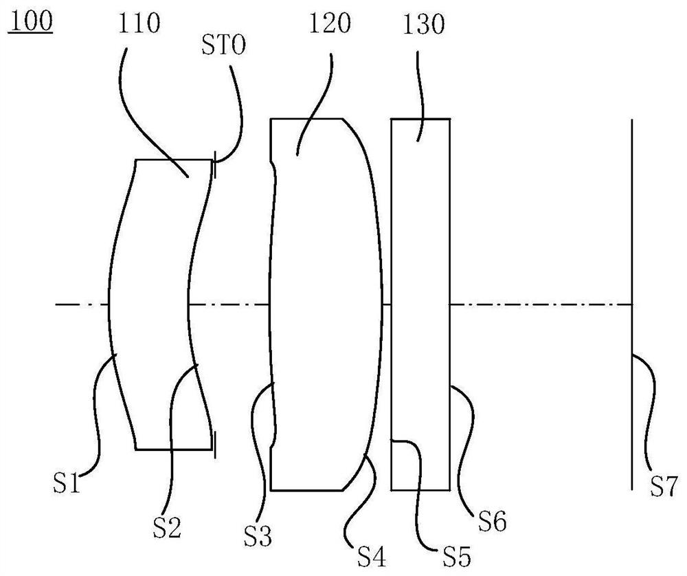
[0083] Please refer to Figure 1 to Figure 2C As shown, the optical system 100 includes a first lens 110 , a stop STO, a second lens 120 , a protective glass 130 and an imaging surface S7 arranged in sequence along the optical axis from the object side to the image side.

[0084] The first lens 110 has positive refractive power, the object side S1 of the first lens 110 is convex at the near optical axis, and the image side S2 of the first lens 110 is concave at the near optical axis. The second lens 120 has positive refractive power. The object side S3 of the second lens 120 is convex at the near optical axis, and the image side S4 of the second lens 120 is also convex at the near optical axis.

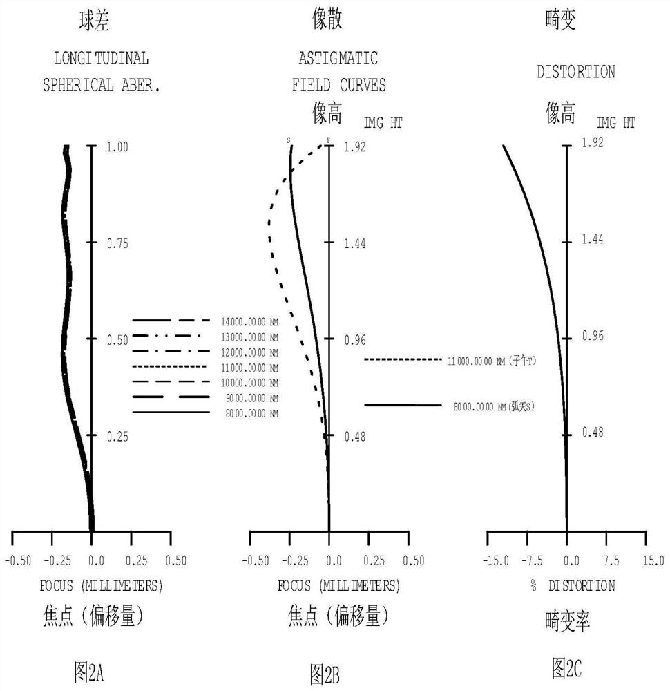
[0085] In the first embodiment, the reference wavelength of the focal length of each lens is 10000.000 nm, and the reference wavelength of the Abbe number and the refractive index are both 587.56 nm. The relevant parameters of the optical system 100 are shown in Table 1, wherein, in ...

Embodiment 2

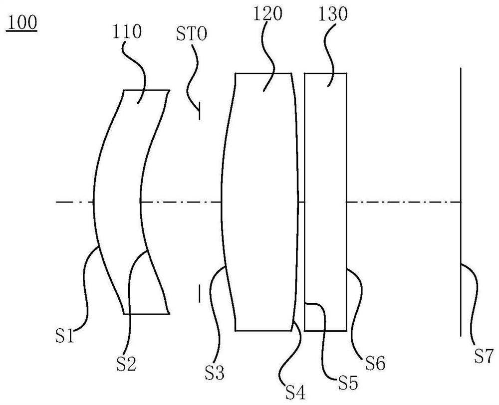
[0099] Please refer to Figure 3 to Figure 4C As shown, the optical system 100 includes a first lens 110 , a stop STO, a second lens 120 , a protective glass 130 and an imaging surface S7 arranged in sequence along the optical axis from the object side to the image side.

[0100] The first lens 110 has positive refractive power, the object side S1 of the first lens 110 is convex at the near optical axis, and the image side S2 of the first lens 110 is concave at the near optical axis. The second lens 120 has positive refractive power. The object side S3 of the second lens 120 is convex at the near optical axis, and the image side S4 of the second lens 120 is also convex at the near optical axis.

[0101] In the second embodiment, the definitions of the relevant parameters of the optical system 100 are the same as those in the first embodiment, and will not be repeated here. The object side S1 of the first lens 110, the image side S2 of the first lens 110, and the object side S3...

Embodiment 3

[0110] Please refer to Figure 5 to Figure 6C As shown, the optical system 100 includes a first lens 110 , a stop STO, a second lens 120 , a protective glass 130 and an imaging surface S7 arranged in sequence along the optical axis from the object side to the image side.

[0111] The first lens 110 has positive refractive power, the object side S1 of the first lens 110 is convex at the near optical axis, and the image side S2 of the first lens 110 is concave at the near optical axis. The second lens 120 has positive refractive power. The object side S3 of the second lens 120 is convex at the near optical axis, and the image side S4 of the second lens 120 is also convex at the near optical axis.

[0112] In the third embodiment, the definitions of the relevant parameters of the optical system 100 are the same as those in the first embodiment, and will not be repeated here. The object side S1 of the first lens 110, the image side S2 of the first lens 110, and the object side S3 ...


PUM


Abstract

The present application discloses an optical system, an imaging module, and electronic equipment. The optical system includes a first lens and a second lens arranged sequentially along the optical axis from the object side to the image side. The first lens has a refractive power, and the first lens has a refractive power. The object side of the lens is convex at the near optical axis, the image side of the first lens is concave at the near optical axis, the second lens has positive refractive power, the object side of the second lens is convex at the near optical axis, and the second The image side of the lens is convex at the near optical axis, the maximum field of view of the optical system is FOV, the diameter of the entrance pupil of the optical system is EPD, and FOV and EPD satisfy the conditional formula: 19.5deg / mm

Description

technical field [0001] The present application relates to the technical field of infrared detection, in particular to an optical system, an imaging module and electronic equipment. Background technique [0002] During the COVID-19 epidemic, infrared thermometers have been widely used in public places such as large shopping malls to measure human body temperature, in order to avoid close-contact measurement and reduce the risk of cross-infection. At present, infrared thermometers on the market usually use diffractive surfaces to improve the imaging quality of the optical system. However, the addition of diffractive surfaces increases the difficulty of processing the lenses in the optical system, thereby increasing the production cost of infrared thermometers. Therefore, how to reduce the cost of the optical system while achieving miniaturization and high imaging quality of the optical system has become an urgent problem to be solved. Contents of the invention [0003] Embo...

Claims


Application Information

Patent Timeline
Patent Type & Authority Patents(China)
IPC IPC(8): G02B13/00G02B13/06G02B13/18G01J5/0806
CPCG02B13/003G02B13/18G02B13/06G01J5/0806
Inventor 乐宇明蔡雄宇许哲源赵迪
Owner JIANGXI JINGCHAO OPTICAL CO LTD
Why Eureka
Try Eureka