
Self-generating device and wireless switch using same

A technology of self-generating and coils, which is applied in the direction of electromechanical devices, coils, circuits, etc., can solve the problems of low power generation efficiency of self-generating devices, unstable control of household appliances, complex magnetic circuits of self-generating devices, etc., and achieve fast manufacturing, closed magnetic The road is simple and the effect of sufficient power

Pending Publication Date: 2020-12-18
CHANGZHOU CIGUANG NEW ENERGY TECH CO LTD
View PDF0 Cites 5 Cited by
  • Summary
  • Abstract
  • Description
  • Claims
  • Application Information

AI Technical Summary

Problems solved by technology

[0002] With the advancement of science and technology, wireless controllers have been widely used in various household appliances. Correspondingly, there have been wireless switches that use wireless switches to control household appliances. The existing wireless switches can be divided into battery-type wireless switches. And self-generating (passive) wireless switches, the use of these wireless switches greatly facilitates people's daily life, but there are many problems in the existing wireless switches: 1. Battery-type wireless switches need to be installed For rechargeable batteries, because the switch is in a wireless connection state, the battery needs to be taken out and charged frequently. Because users often forget to charge, it is misjudged as a power failure when using electrical appliances, which is inconvenient to use; 2. The existing self-generating wireless switch automatically The magnetic circuit of the generating device is complex, which is inconvenient to manufacture and increases the manufacturing cost; 3. The self-generating device in the existing self-generating wireless switch has low power generation efficiency, weak current, and insufficient power supply, resulting in unstable control of household appliances; 4. In some self-generating wireless switches, the components used for assembly between the permanent magnet assembly (permanent magnet and soft magnetic frame) and the coil assembly (soft magnetic plate and coil) are complex in structure and inconvenient to manufacture

Method used


Image

  • Self-generating device and wireless switch using same
  • Self-generating device and wireless switch using same
  • Self-generating device and wireless switch using same

Examples


Embodiment 1

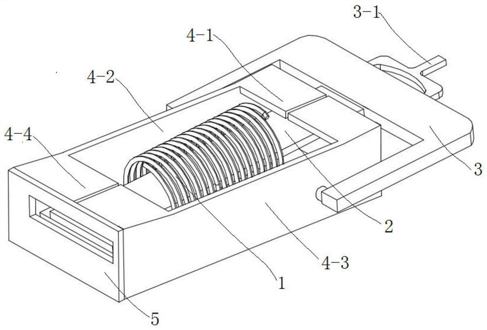
[0037] combine figure 1, a self-generating device of the present embodiment includes a coil assembly and a permanent magnet assembly, the coil assembly includes a soft magnetic plate 2 and a coil 1, the soft magnetic plate 2 can be rotated up and down, and the coil 1 is wound on the soft magnetic plate 2 middle part;

[0038] The permanent magnet assembly comprises the first soft magnetic frame, the first permanent magnet 6 and the second permanent magnet 7, and the first soft magnetic frame includes the first upper soft magnetic plate 4-4, the first lower soft magnetic plate 4-5, the second Lower soft magnetic plate 4-6, the second upper soft magnetic plate 4-1, the first front soft magnetic plate 4-3 and the first rear soft magnetic plate 4-2; the first front soft magnetic plate 4-3, the first Rear soft magnetic plate 4-2 is respectively arranged on the front and rear sides of soft magnetic plate 2; side; the front and rear ends of the first upper soft magnetic plate 4-4 a...

Embodiment 2

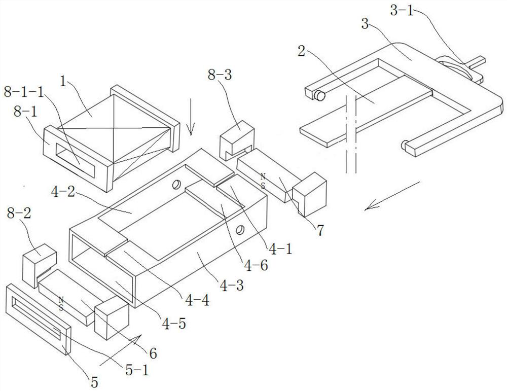
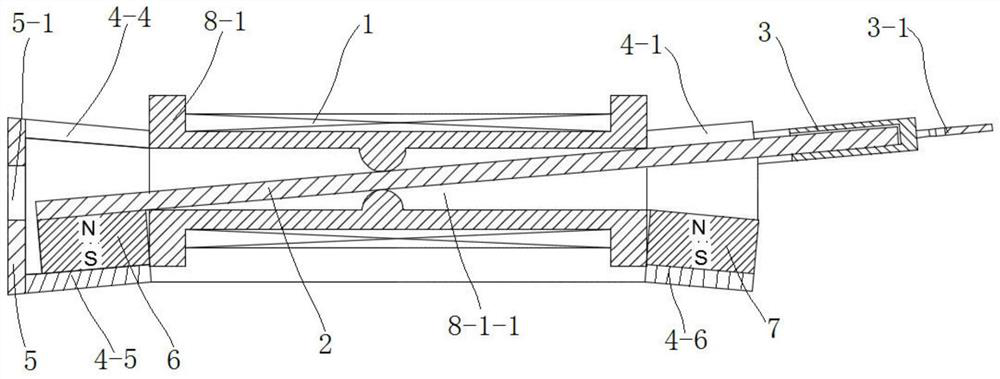
[0045] combine Figure 4 , the basic structure of a self-generating device of this embodiment is the same as that of Embodiment 1, the difference is that the first permanent magnet 6 is adsorbed on the first lower soft magnetic plate 4-5, and the second permanent magnet 7 is adsorbed on the first lower soft magnetic plate 4-5. On the upper soft magnetic plate 4-4, the distance between the first permanent magnet 6 and the second permanent magnet 7 is equal to the distance between the second upper soft magnetic plate 4-4 and the second lower soft magnetic plate 4-5;

[0046] In the initial state, the left and right ends of the soft magnetic plate 2 are respectively in contact with the first permanent magnet 6 and the second upper soft magnetic plate 4-1 to form a third closed magnetic circuit; when the soft magnetic plate 2 rotates relative to the permanent magnet assembly , the left and right ends of the soft magnetic plate 2 are respectively in contact with the second permanen...

Embodiment 3

[0050] combine Figure 7, a self-generating device of the present embodiment includes a coil assembly and a permanent magnet assembly, the coil assembly includes a soft magnetic plate 2 and a coil 1, the soft magnetic plate 2 can be rotated up and down, and the coil 1 is wound on the soft magnetic plate 2 The middle part; the permanent magnet assembly includes the second soft magnetic frame, the first permanent magnet 6 and the second permanent magnet 7, and the second soft magnetic frame includes the third upper soft magnetic plate 10-3, the third lower soft magnetic plate 10-4, The fourth lower soft magnetic plate 10-2 and the fourth upper soft magnetic plate 10-1, the third upper soft magnetic plate 10-3 and the third lower soft magnetic plate 10-4 are relatively arranged on the left end of the soft magnetic plate 2 respectively. The upper and lower sides, the left end of the third upper soft magnetic plate 10-3 and the left end of the third lower soft magnetic plate are co...


PUM


Abstract

The invention discloses a self-generating device and a wireless switch using the same, which belong to the field of self-generating devices. The self-generating device comprises a coil assembly and apermanent magnet assembly. In the initial state, the left end and the right end of a soft magnetic plate make contact with a first permanent magnet and a second upper soft magnetic plate respectivelyto form a first closed magnetic circuit; after the soft magnetic plate rotates relative to the permanent magnet assembly, the left end and the right end of the soft magnetic plate are respectively contacted with the first upper soft magnetic plate and the second permanent magnet to form a second closed magnetic circuit; the direction of magnetic force lines passing through the soft magnetic platein the first closed magnetic circuit is opposite to that of magnetic force lines passing through the soft magnetic plate in the second closed magnetic circuit, and the coil generates power according to the electromagnetic induction principle. The wireless switch comprises a radio frequency control panel, a switch used for controlling electric equipment and the self-generating device, a coil of theself-generating device is electrically connected with the radio frequency control panel, and passive wireless switch control can be achieved.

Description

technical field [0001] The present invention relates to a power generating device and a wireless switch with the same, more specifically, to a self-generating device and a wireless switch using the same. Background technique [0002] With the advancement of science and technology, wireless controllers have been widely used in various household appliances. Correspondingly, there have been wireless switches that use wireless switches to control household appliances. The existing wireless switches can be divided into battery-type wireless switches. And self-generating (passive) wireless switches, the use of these wireless switches greatly facilitates people's daily life, but there are many problems in the use of existing wireless switches: 1. Battery-type wireless switches need to be installed For rechargeable batteries, because the switch is in a wireless connection state, the battery needs to be taken out and charged frequently. Because users often forget to charge, it is mis...

Claims


Application Information

Patent Timeline
Patent Type & Authority Applications(China)
IPC IPC(8): H02K35/02H02K1/34G08C17/02
CPCH02K35/02H02K1/34G08C17/02H01F5/02H02K35/06H04B1/1607H01F2005/027
Inventor 李春光
Owner CHANGZHOU CIGUANG NEW ENERGY TECH CO LTD
Learn More