
Elevator shaft traction rotary telescopic construction hoist and mounting and using method thereof

A technology for construction elevators and elevator shafts, which is applied to elevators, transportation, and packaging in buildings. It can solve the problems of wasting manpower and material resources, inconvenient operation, and safety, and achieves saving manpower and material resources, shortening the construction period, and simple structure. Effect

Pending Publication Date: 2020-12-22
马利群
View PDF8 Cites 0 Cited by
  • Summary
  • Abstract
  • Description
  • Claims
  • Application Information

AI Technical Summary

Problems solved by technology

[0002] In the construction of high-rise buildings, the construction hoist for the elevator shaft usually adopts a one-shaped integral beam. During the use of the one-shaped integral beam, the beam body should be hung obliquely and inserted into the door opening when the one-shaped integral beam is installed and heightened. Inside, this kind of inclined suspension is not only inconvenient to operate, but also has potential safety hazards. It is necessary to support a horse stool under the sky beam. The weight of the 80kg horse stool needs to be carried repeatedly by manpower, which is too slow and wastes manpower. Material resources and construction period cannot be guaranteed. In addition, in the prior art, it is difficult to ensure that the main girder and the telescopic beam are on the same horizontal plane when the telescopic construction elevator is stretched, resulting in an unstable structure when the construction elevator is suspended, and there are certain safety hazards. Therefore, the present invention proposes an elevator shaft traction rotary telescopic construction hoist and its installation and use method that can solve the above problems

Method used

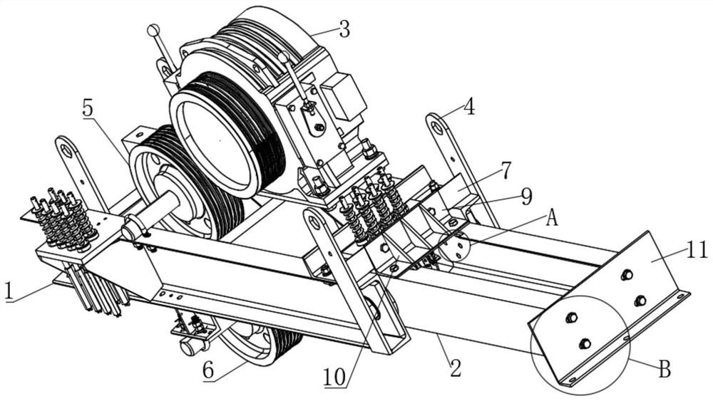
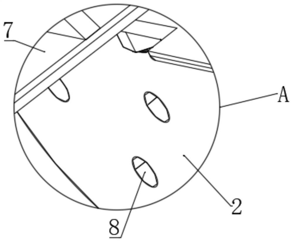
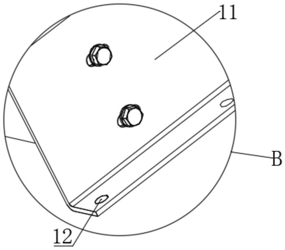

Image

  • Elevator shaft traction rotary telescopic construction hoist and mounting and using method thereof
  • Elevator shaft traction rotary telescopic construction hoist and mounting and using method thereof
  • Elevator shaft traction rotary telescopic construction hoist and mounting and using method thereof

Examples


Embodiment Construction

[0031] The following will clearly and completely describe the technical solutions in the embodiments of the present invention with reference to the accompanying drawings in the embodiments of the present invention. Obviously, the described embodiments are only some, not all, embodiments of the present invention. Based on the embodiments of the present invention, all other embodiments obtained by persons of ordinary skill in the art without making creative efforts belong to the protection scope of the present invention.

[0032] In the description of the present invention, it should be noted that the orientation or positional relationship indicated by the terms "vertical", "upper", "lower", "horizontal" etc. is based on the orientation or positional relationship shown in the drawings, and is only In order to facilitate the description of the present invention and simplify the description, it does not indicate or imply that the device or element referred to must have a specific o...


PUM


Abstract

The invention discloses an elevator shaft traction rotary telescopic construction hoist. The elevator shaft traction rotary telescopic construction hoist comprises a main beam, wherein a front beam isrotatably connected to one end of the main beam; a mounting plate is fixedly arranged at one end, close to the front beam, above the main beam; limiting angle steel is fixedly arranged above the front beam; one side, close to the main beam, of the limiting angle steel is abutted against one side of the mounting plate; a plurality of front beam positioning holes are formed in the front beam; and afront beam telescopic sealing plate is fixedly arranged on one side, away from the main beam, of the front beam. The front beam can rotate at one end of the main beam to stretch out and draw back; the elevator shaft traction rotary telescopic construction hoist is relatively convenient to use, and easy to operate; the front beam and the main beam are pulled upwards to be located on the same horizontal plane; the limiting angle steel is used for limiting the upward rotating range of the front beam; the structure is simple; and the structure is more stable when the construction hoist is used for hanging.

Description

technical field [0001] The invention relates to the technical field of building construction machinery and equipment, in particular to an elevator shaft traction rotary telescopic construction hoist and an installation and use method thereof. Background technique [0002] In the construction of high-rise buildings, the construction hoist for the elevator shaft usually adopts a one-shaped integral beam. During the use of the one-shaped integral beam, the beam body should be hung obliquely and inserted into the door opening when the one-shaped integral beam is installed and heightened. Inside, this kind of inclined suspension is not only inconvenient to operate, but also has potential safety hazards. It is necessary to support a horse stool under the sky beam. The weight of the 80kg horse stool needs to be carried repeatedly by manpower, which is too slow and wastes manpower. Material resources and construction period cannot be guaranteed. In addition, in the prior art, it is ...

Claims


Application Information

Patent Timeline
Patent Type & Authority Applications(China)
IPC IPC(8): B66B11/04B66B11/00
CPCB66B11/04B66B11/0035B66B11/00
Inventor 马利群
Owner 马利群
Learn More