A spatiotemporal tomography method of vibration field in complex shallow underground space

A tomography and space technology, applied in the field of blasting vibration testing technology and passive positioning, can solve the problems of low source positioning accuracy, poor source positioning robustness, and inability to guarantee positioning accuracy, and reduce the number of tests and the number of sensors. , The effect of improving the energy focusing intensity and improving the recognition accuracy

Active Publication Date: 2022-07-08
ZHONGBEI UNIV
View PDF8 Cites 0 Cited by
  • Summary
  • Abstract
  • Description
  • Claims
  • Application Information

AI Technical Summary

Problems solved by technology

[0005] Due to the complexity of the underground medium, the small number of sensors and the random layout when locating the shallow seismic source, the imaging accuracy of the underground energy field is not high, and the positioning accuracy of the seismic source is low;
[0006] Researchers use the swarm intelligence algorithm to quickly locate the energy focal point. This method has certain blindness and randomness when searching for the focal point, which leads to unstable recognition of the focal point, poor robustness of source positioning, and positioning accuracy cannot be guaranteed. Ultimately, it is impossible to achieve effective space-time field reconstruction
[0007] When using a supervised deep learning method to locate the detonation point, it is necessary to preset multiple seismic source bombs to train the network model, resulting in long test periods and high test costs
[0008] Aiming at the problems of low accuracy and poor stability of underground shallow seismic source positioning, the present invention proposes a seismic source positioning method based on unsupervised deep learning

Method used


Image

  • A spatiotemporal tomography method of vibration field in complex shallow underground space
  • A spatiotemporal tomography method of vibration field in complex shallow underground space
  • A spatiotemporal tomography method of vibration field in complex shallow underground space

Examples


Embodiment Construction

[0024] In order to make the purpose, content and advantages of the present invention clearer, the specific embodiments of the present invention will be described in further detail below.

[0025] A method for spatiotemporal tomography of a vibration field in an underground shallow complex space proposed by the present invention is characterized in that it specifically includes the following steps:

[0026] S1, lay out the vibration sensor array

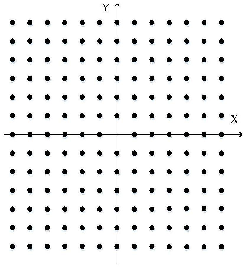
[0027] Select a point at the center of the monitoring area as the coordinate origin, establish a Cartesian coordinate system, set n=168 sensors, take the coordinate origin as the center, and arrange the vibration sensors on the ground with an interval of 1m to form an equidistant square array. Beidou obtains the coordinate information of each sensor X i =(x i ,y i ,z i )(i=1,2,3,...,n);

[0028] S2. Generate a learning sample based on energy information, as follows:

[0029] S2.1 Obtain the actual source signal: use the vibratio...


PUM


Abstract

The invention relates to a time-space tomography method of vibration field in complex shallow underground space, which combines autocorrelation imaging technology to eliminate noise of vibration signal, improves the resolution of energy field imaging at each moment, and uses cross-correlation imaging technology to eliminate reverse time Imaging interference caused by backpropagation. Using the time-varying characteristics of the explosion vibration signal, the length of the time window is set, and the energy field information within the length of the time window is linearly superimposed. The invention improves the energy focusing intensity of the instantaneous energy field, converts the three-dimensional energy field image in the space domain into a three-dimensional energy field image sequence in the time-space domain, and improves the quantity and quality of the energy field images. Taking advantage of the generative adversarial network, the important spatiotemporal information of the three-dimensional energy field is learned by itself in the process of generative adversarial, and the stability of the source location is improved. Using the advantages of generative adversarial network, self-learning, self-confrontation, and self-adjustment, the number of trials and the number of sensors is reduced, and the location of the hypocenter under the preset 1-time starting point is realized.

Description

technical field [0001] The invention belongs to the fields of blasting vibration testing technology and passive positioning technology, and particularly relates to a time-space tomography imaging method of vibration field in complex shallow underground space. Background technique [0002] The spatiotemporal distribution of the explosive power field is to reconstruct the intensity distribution after the explosion by using the explosion performance parameters such as overpressure, stress wave energy, kinetic energy and other physical parameters of the explosion. This method is an important means to realize the evaluation of the damage efficiency of underground explosions. [0003] In the process of spatial-temporal reconstruction of the explosive power field, the accurate measurement of the location of the underground initiation point is the key to the reconstruction of the spatial-temporal field. Compared with the seismic source positioning of large-area, large-depth, long-t...

Claims


Application Information

Patent Timeline
Patent Type & Authority Patents(China)
IPC IPC(8): G01V1/30G01V1/36G06N3/04G06N3/08
CPCG01V1/30G01V1/36G06N3/088G01V2210/65G01V2210/32G06N3/045
Inventor 李剑李传坤曹凤虎郭亚丽韩焱王黎明韩星程
Owner ZHONGBEI UNIV
Why Eureka
Try Eureka