Supercharge Your Innovation With Domain-Expert AI Agents!

A butterfly valve, a method for rotatably locking a disc of a butterfly valve and use of a butterfly valve

A technology of butterfly valves and butterfly plates, which is applied in the direction of lifting valves, valve devices, engine components, etc., can solve the problems of incorrect positioning of parts, difficult correct installation and disassembly of wedges, etc., and achieve safe locking, firm fixing, and risk reduction Effect

Pending Publication Date: 2020-12-22
AVK HLDG AS
View PDF10 Cites 0 Cited by
  • Summary
  • Abstract
  • Description
  • Claims
  • Application Information

AI Technical Summary

Problems solved by technology

However, such wedges are difficult to install correctly, and even more difficult to remove
Dirt trapped between the wedge and the shaft, improper positioning of parts when installing the wedge or other components can all cause play between the wedge and the shaft, creating backlash

Method used


Image

  • A butterfly valve, a method for rotatably locking a disc of a butterfly valve and use of a butterfly valve
  • A butterfly valve, a method for rotatably locking a disc of a butterfly valve and use of a butterfly valve
  • A butterfly valve, a method for rotatably locking a disc of a butterfly valve and use of a butterfly valve

Examples


Embodiment Construction

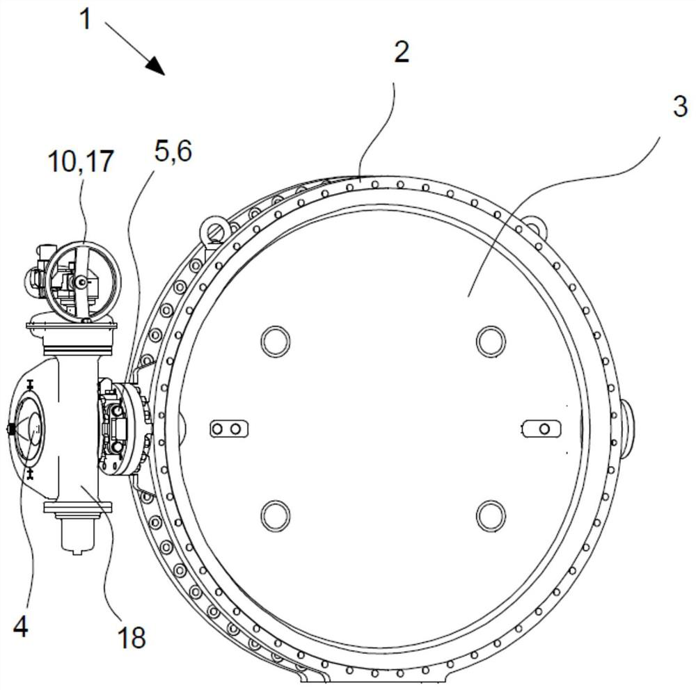
[0062] figure 1 The butterfly valve 1 is shown, as seen in perspective view.

[0063] In this embodiment, the butterfly valve 1 includes a butterfly plate 3 suspended on both sides but only provided with a transmission device 10 on one side. However, in another embodiment, the butterfly plate 3 could be provided with transmissions 10 on both sides, or the butterfly plate 3 would only be suspended on one side, for example, if the transmission 10 was arranged on the top of the butterfly plate 3 instead of the side.

[0064] In this embodiment, the drive means 10 comprise a handle 17 arranged to act on the drive shaft 4 via a gear 18, in this case a worm gear. However, in another embodiment, the transmission 10 may comprise a lever, drive, motor, or other device and / or the transmission 10 may be adapted in another manner (such as by a chain or belt drive, planetary gears, spur gears, or other device). ) and / or butterfly valve 1 does not contain gear 18.

[0065] In this embodi...


PUM


Abstract

Disclosed is a butterfly valve (1)comprising a valve housing (2)and a rotatable disc (3)arranged to rotate between a blocking position, in which the disc (3)will block flow through the housing (2), and an open position in which the disc (3)will enable flow through the housing (2). The butterfly valve (1)further comprises a drive shaft (4)connected to the disc (3)and through which rotation of the disc (3)between the blocking position and the open position is at least partly enabled and the butterfly valve (1)comprises drive shaft locking means (5)arranged to lock the disc (3)against rotation atleast in the blocking position or the open position, wherein the drive shaft locking means (5)comprises a removable locking pawl (6)including pawl engagement means (7)arranged to engage shaft engagement means (8)of the drive shaft (4), wherein the locking pawl (6)is maintained in the engagement by means of separate mechanical fastening means (9)arranged to releasably fix the locking pawl (6)to form backlash-freedrive shaft locking means (5). A method for rotatably locking a disc (3)of a butterfly valve (1)and use of a butterfly valve (1)is also disclosed.

Description

technical field [0001] The present invention relates to a butterfly valve comprising a valve housing and a rotatable disc arranged to rotate between a blocking position and an open position, in which the disc blocks fluid flow through the housing and in an open position, the disc prevents the fluid from flowing through the housing able to flow through the shell. [0002] The invention also relates to a method for rotatably locking the butterfly plate of the butterfly valve, and also discloses the application of the butterfly valve. Background technique [0003] A butterfly valve is a valve that isolates or regulates the flow of a fluid by rotating a disc positioned in the fluid between parallel and perpendicular positions to the fluid. Unlike ball valves, discs are always in the fluid, so even when open, there is a pressure drop. [0004] In operation, when the butterfly plate rotates a quarter of a turn, the butterfly valve is fully opened or closed. "Butterfly" refers t...

Claims


Application Information

Patent Timeline
IPC IPC(8): F16K1/22
CPCF16K1/221
Inventor 尼古拉斯·科尼利厄斯·德克勒克
Owner AVK HLDG AS
Features
  • R&D
  • Intellectual Property
  • Life Sciences
  • Materials
  • Tech Scout
  • Unparalleled Data Quality
  • Higher Quality Content
  • 60% Fewer Hallucinations
Learn More