Eureka AIR delivers breakthrough ideas for toughest innovation challenges, trusted by R&D personnel around the world.

A kind of automatic visual inspection equipment and inspection method for precision electronic stamping parts

A visual inspection, precision electronic technology, applied in measuring devices, chemical instruments and methods, cleaning methods and utensils, etc., can solve the problems of missed detection, misjudgment, poor detection accuracy, unfavorable production control, etc., to achieve stability and reliability. High performance, reduce production costs, and facilitate production control

Active Publication Date: 2022-07-19
昆山捷胜精密电子有限公司
View PDF0 Cites 0 Cited by
  • Summary
  • Abstract
  • Description
  • Claims
  • Application Information

AI Technical Summary

Problems solved by technology

[0004] However, for the detection of stamping parts, the traditional detection method of manually passing through the measuring fixture, etc., takes up a lot of manpower, takes a long time, is labor-intensive, inconvenient to operate, is not conducive to production control, and has poor detection accuracy. Long-term work is prone to fatigue, and it is easy to cause missed inspections and misjudgments, which will affect the overall quality of the product, low production efficiency, high production cost, and reduce the competitiveness of the product.

Method used


Image

  • A kind of automatic visual inspection equipment and inspection method for precision electronic stamping parts
  • A kind of automatic visual inspection equipment and inspection method for precision electronic stamping parts
  • A kind of automatic visual inspection equipment and inspection method for precision electronic stamping parts

Examples


Embodiment 1

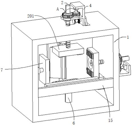
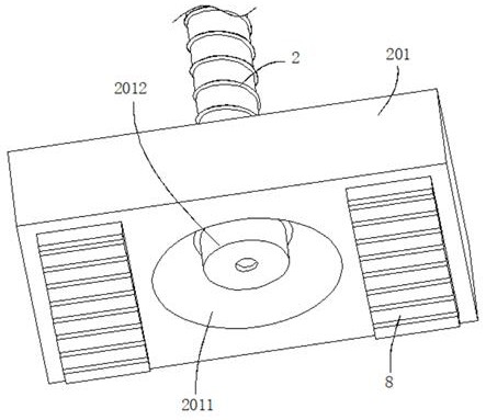
[0038] refer to Figure 1-5 , an automatic visual inspection equipment for precision electronic stamping parts, including a fixing frame 1, the outer wall of the fixing frame 1 is connected with two sets of positioning mechanisms, the positioning mechanism includes a threaded rod 2, the threaded rod 2 is threadedly connected in the fixing frame 1, and the threaded rod 2 A first clamping plate 201 is connected to the outer wall, a groove 2011 is drilled on the outer wall of the first clamping plate 201, a camera 2012 is connected to the inner wall of the groove 2011, and a moving rod 202 is connected to the end of the threaded rod 2 away from the first clamping plate 201, The outer wall of the moving rod 202 is sleeved with a sleeve 3, the moving rod 202 is slidably connected in the sleeve 3, the outer wall of the fixed frame 1 is connected with a support seat 4, the sleeve 3 is rotatably connected in the support seat 4, and the outer wall of the support seat 4 is connected with...

Embodiment 2

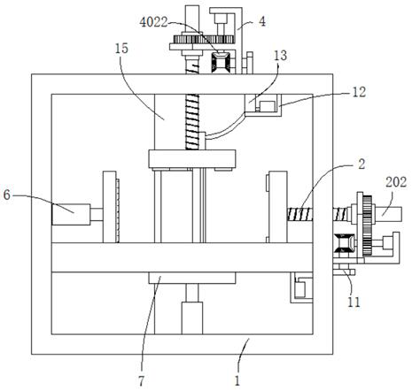
[0041] refer to figure 1 , figure 2 , Image 6 , Figure 7 and Figure 8 , an automatic visual inspection equipment for precision electronic stamping parts, which is basically the same as Embodiment 1. Further, the end of the rotating shaft 402 away from the motor 401 passes through the support base 4 and is connected with a first bevel gear 4022. The outer walls on both sides of the gear 4022 are meshed with a second bevel gear 9, the outer walls of the two second bevel gears 9 are connected with a rotating rod 10, the rotating rod 10 is rotatably connected in the support seat 4, and the outer wall of the rotating rod 10 is connected with a cam 11, fixed The inner wall of the frame 1 is connected with a support plate 12, the outer wall of the support plate 12 is connected with a working pipe 13 and a water tank 14, a water inlet pipe 141 is connected between the working pipe 13 and the water tank 14, a piston 131 is slidably connected to the inner wall of the working pipe...

Embodiment 3

[0044] refer to Figure 1-8 , an automatic visual inspection equipment for precision electronic stamping parts, which is basically the same as Embodiment 1. Further, the outer wall of the sleeve 3 is connected with a guide strip 301, and the outer wall of the moving rod 202 is drilled with a guide groove that matches the guide strip 301. 2021; improve the stability of the movement of the moving rod 202 in the casing 3.

[0045] The invention also discloses a detection method of automatic visual detection equipment for precision electronic stamping parts, comprising the following steps:

[0046] S1: Place the stamping part on the second clamping plate 7 of the first group of positioning mechanisms, control the first group of positioning mechanisms to work, make the motor 401 run, the motor 401 drives the first gear 4021 to rotate through the rotating shaft 402, the first gear 4021 meshes with the second gear 5, so that the second gear 5 drives the casing 3 to rotate, so that t...


PUM


Abstract

The invention discloses an automatic visual inspection equipment and a detection method for precision electronic stamping parts, and belongs to the technical field of inspection equipment. A fully automatic visual inspection equipment for precision electronic stamping parts, comprising a fixing frame, the outer wall of the fixing frame is connected with two sets of positioning mechanisms, the positioning mechanism comprises a threaded rod, the threaded rod is threadedly connected in the fixing frame, and the outer wall of the threaded rod is connected with a first clamping mechanism The outer wall of the first clamping plate has a groove, the inner wall of the groove is connected with a camera, the end of the threaded rod away from the first clamping plate is connected with a moving rod, the outer wall of the moving rod is sleeved with a sleeve, and the moving rod is slidably connected to the sleeve. Inside the tube, the outer wall of the fixing frame is connected with a support seat, the sleeve is rotatably connected in the support seat, and the outer wall of the support seat is connected with a motor; the invention can realize comprehensive and accurate automatic shooting and detection of products, with high detection accuracy, high speed and stability. And high reliability, improve production efficiency and overall product quality, reduce production costs, and facilitate production control.

Description

technical field [0001] The invention relates to the technical field of detection equipment, in particular to a fully automatic visual detection equipment and detection method for precision electronic stamping parts. Background technique [0002] With the continuous progress of society and the rapid development of science and technology, the market demand for many products is increasing, and the requirements are getting higher and higher. Therefore, it is necessary to ensure product quality and improve production efficiency to meet market demand. Stamping is a forming and processing method of stamping parts with the required shape and size by applying external force to sheets, strips, pipes and profiles by means of presses and dies to cause plastic deformation or separation. [0003] At present, after the stamping product is processed, it is usually necessary to inspect the product to check whether the appearance size of the product meets the standard, whether the appearance ...

Claims


Application Information

Patent Timeline
Patent Type & Authority Patents(China)
IPC IPC(8): B21C51/00B08B1/02B08B3/08B08B13/00G01N21/95G01B11/16G01N21/88
CPCB21C51/00B08B1/002B08B1/02B08B1/006B08B3/041B08B3/08B08B13/00G01N21/95G01B11/16G01N21/8806
Inventor 蒋建新
Owner 昆山捷胜精密电子有限公司
Why Eureka
Eureka Blog
Learn More