Hoop bending device

A bending device and bending technology, applied in the direction of feeding device, positioning device, storage device, etc., can solve the problems of manual feeding and retrieving, and achieve the effect of safe use of equipment and improvement of safety

Pending Publication Date: 2020-12-25
欧行
View PDF7 Cites 3 Cited by
  • Summary
  • Abstract
  • Description
  • Claims
  • Application Information

AI Technical Summary

Problems solved by technology

[0005] In order to overcome the shortcomings of the current hoop production bending device that requires manual feeding and retrieving, the technical problem of the present invention is to provide a hoop bending device that can automatically perform loading and unloading

Method used


Image

  • Hoop bending device
  • Hoop bending device
  • Hoop bending device

Examples


Embodiment 1

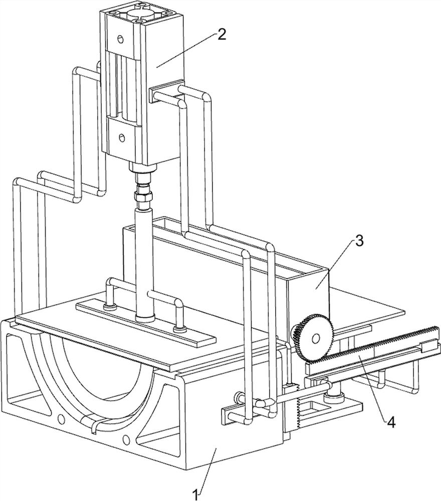
[0020] A hoop bending device, such as Figure 1-3 As shown, it includes a workbench 1, a bending assembly 2 and a feeding assembly 3. The upper part of the workbench 1 is installed with a bending assembly 2 that is bent by lifting and lowering. Feeding component 3 of the material.

[0021] When it is necessary to use this device to bend the hoop material, first place the material to be bent in the feeding assembly 3, then push the material to the top of the workbench 1 through the feeding assembly 3, and then pass the bending assembly 2 Bending the hoop material, and after the hoop material is bent, remove the bent material.

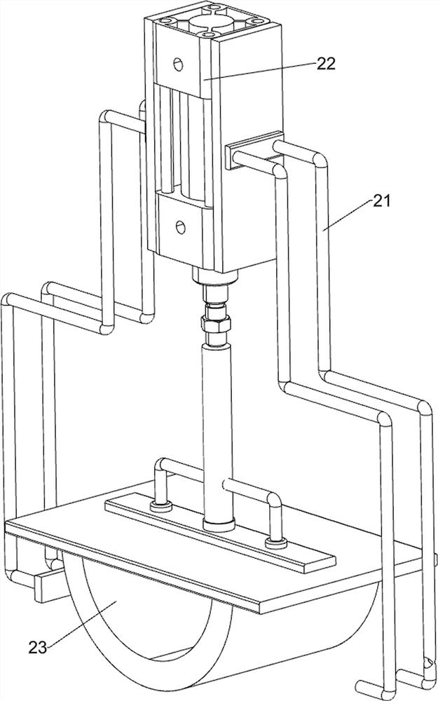
[0022] The bending assembly 2 includes a mounting frame 21, a cylinder 22 and an arc plate 23. The front and rear sides of the workbench 1 are fixed with the mounting frame 21 through bolts, the top of the mounting frame 21 is fixed with a cylinder 22 through bolts, and the bottom of the cylinder 22 An arc-shaped plate 23 is fixedly connected by bolts,...

Embodiment 2

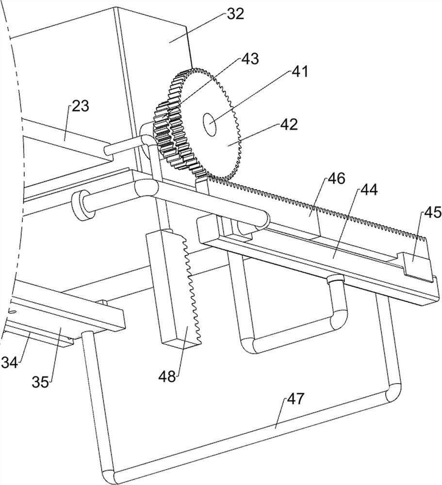
[0027] On the basis of Example 1, such as figure 1 , 4 Shown in and 5, also includes moving assembly 4, is provided with the moving assembly 4 that moves by rotation between material storage frame 32 and workbench 1 front side, and moving assembly 4 includes rotating shaft 41, big gear 42, small Gear 43, slide rail 44, slide block 45, the first tooth bar 46, the first connecting rod 47 and the second tooth bar 48, material storage frame 32 front side lower parts are provided with rotating shaft 41 by bearing seat rotation type, rotating shaft 41 The front end key is connected with a large gear 42, the middle part of the rotating shaft 41 is keyed with a pinion 43, and the right part of the front side of the workbench 1 is fixedly connected with a slide rail 44 by screws, and a slide block 45 is provided for sliding on the slide rail 44, and the slide block 45 The top is fixed with a first rack 46 by bolts, the first rack 46 meshes with the large gear 42, the first connecting ...


PUM


Abstract

The invention relates to a bending device, in particular to a hoop bending device. The hoop bending device can automatically conduct feeding and discharging. The hoop bending device comprises a workbench, a bending assembly and a feeding assembly, wherein the bending assembly is installed on the workbench and conducts bending in a lifting mode, and the feeding assembly is installed on the workbench and conducts feeding in a sliding mode. According to the hoop bending device, materials can be rapidly bent through the bending assembly, the materials can be rapidly placed through the feeding assembly, the materials can be automatically put down through a moving assembly, and equipment is safer to use; and the bent materials can be automatically pushed out through a second connecting rod and apush block, and the safety of the equipment is further improved.

Description

technical field [0001] The invention relates to a bending device, in particular to a hoop bending device. Background technique [0002] A hoop is a component that hugs or hoops another material with one material. It belongs to fasteners. When making the hoop, it is necessary to bend the material. [0003] The patent authorization announcement number is CN207071602U, which discloses a hoop bending press, including a base and a machine head fixed to the base through a column. The machine head is provided with a main oil cylinder, and the main oil cylinder is connected with an upper mold. A lower mold fixed on the base is provided below the upper mold. The upper mold is arc-shaped with the arc facing downward, and the curvature of the arc is consistent with the hoop. The lower mold includes a left module and a left module arranged symmetrically. The right module, the opposite surfaces of the left module and the right module form a trumpet shape with a large upper part and a ...

Claims


Application Information

Patent Timeline
Patent Type & Authority Applications(China)
IPC IPC(8): B21D11/00B21D11/22B21D43/02B21D45/04
CPCB21D11/00B21D11/22B21D43/02B21D45/04
Inventor 欧行
Owner 欧行
Why Eureka
Try Eureka