Steel bar bending device and method and application of steel bar bending device

A bending device and steel bar technology, which is applied in the field of steel bar bending devices, can solve the problems of limited protruding length of steel bars at beam ends and narrow bending space of steel bars, etc.

Active Publication Date: 2018-09-04
CHONGQING UNIVERSITY OF SCIENCE AND TECHNOLOGY
View PDF25 Cites 3 Cited by
  • Summary
  • Abstract
  • Description
  • Claims
  • Application Information

AI Technical Summary

Problems solved by technology

However, due to the fact that the components at the joints are close to each other, and there are many scaffolds erected on the assembly construction site, the extension length of the steel bars at the beam ends is limited, and the bending space of the steel bars is very narrow. The traditional traditional big arm bending method cannot be used. Reference documents CN201710184489, CN20171039915 , CN201710984789, CN201711151671, CN201711204685, and CN201711216939 are aimed at bending steel bars in steel bar processing sheds in cast-in-place buildings. Apparatus and method for reinforcement

Method used


Image

  • Steel bar bending device and method and application of steel bar bending device
  • Steel bar bending device and method and application of steel bar bending device
  • Steel bar bending device and method and application of steel bar bending device

Examples


Embodiment Construction

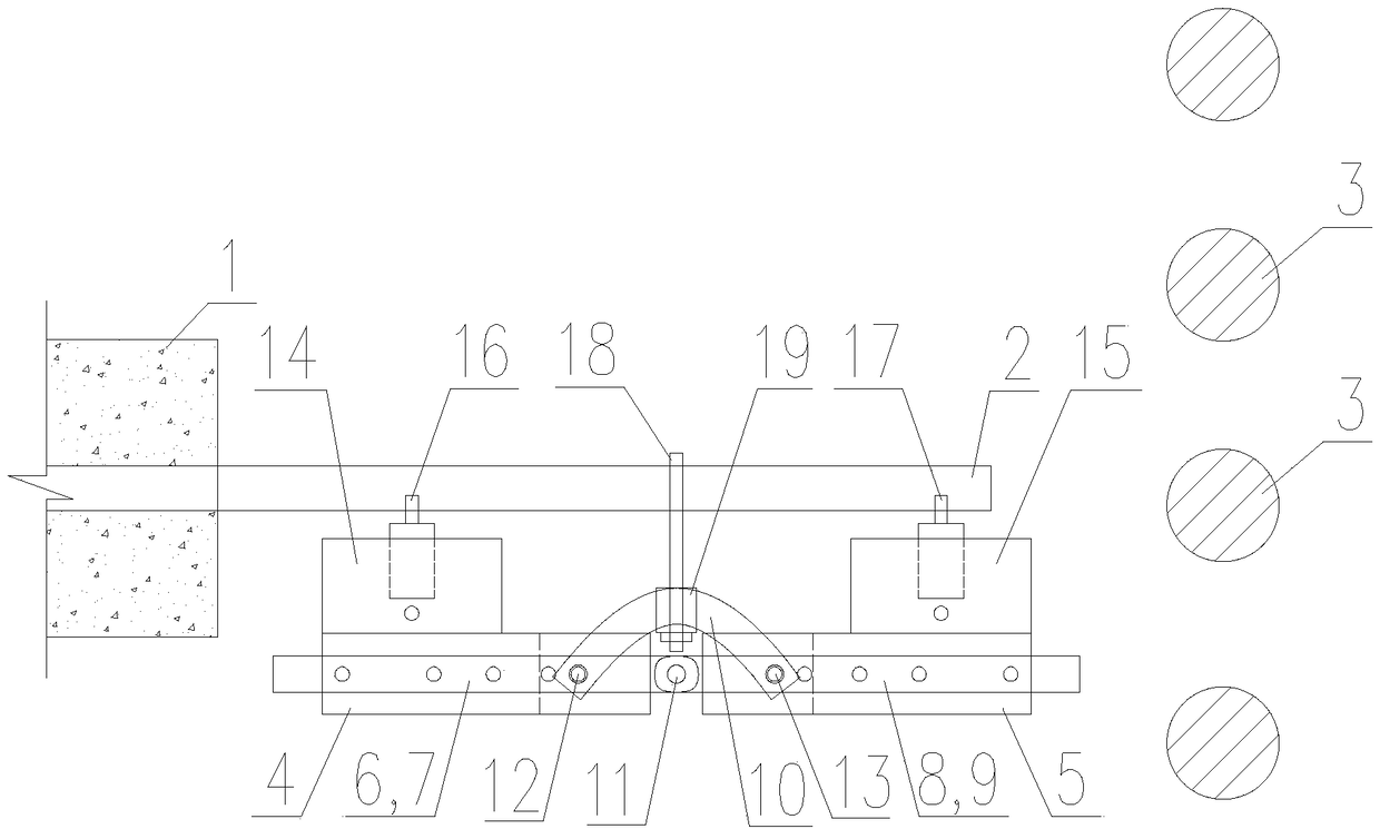
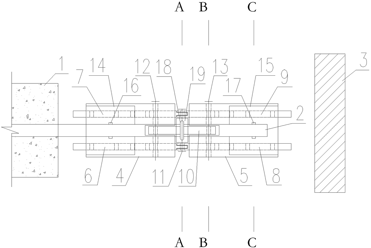
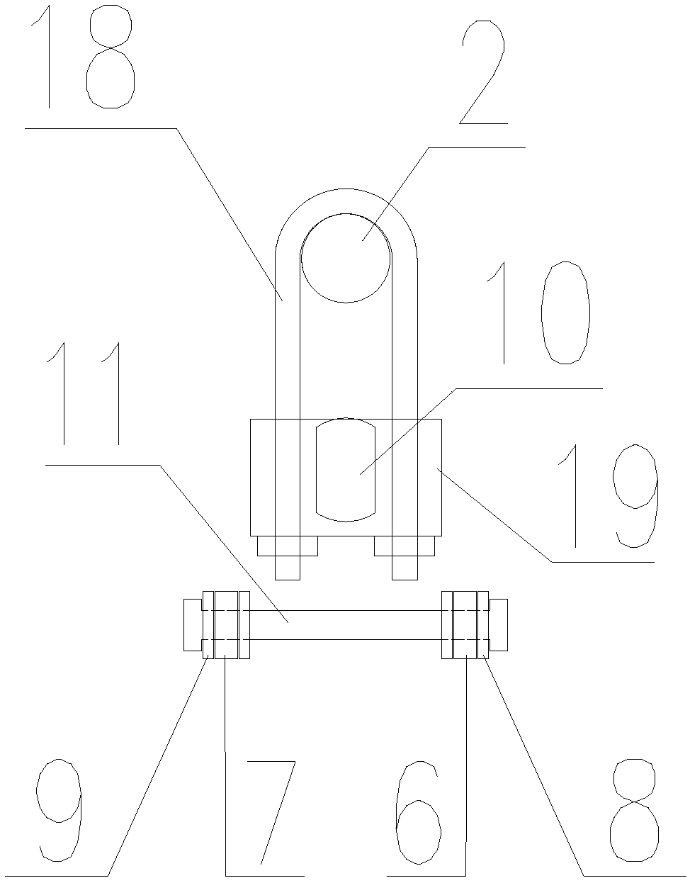
[0033] see Figure 1-Figure 5 , a steel bar bending device, comprising two perforated supports, two sliding chain bars parallel to each other are slidably fitted in the perforations of each perforated support, and the two sliding chain bars on the two perforated supports The opposite ends are hinged by a chain rod rotating shaft. The two perforated supports can rotate mutually through the hinge points of the sliding chain rods, the middle parts of the opposite ends of the two perforated supports are vertically provided with installation gaps, and the two ends of a tensile bending rod are respectively inserted into the two perforated supports. In the installation gap of the seat, the two perforated supports are respectively provided with a socket, the sliding chain rod is provided with a plurality of sockets in the axial direction, and the two ends of the tensile bending rod inserted into the installation gap are respectively provided with There is a socket, and any socket on ...


PUM


Abstract

The invention discloses a steel bar bending device and method and application of the steel bar bending device. By usage of the device and the method, in the narrow space, air pressure can be utilizedas power, and a steel bar is simply and rapidly bent by any angle. The device is mainly composed of two punching supports, four sliding chain rods, an anti-tension curved bar, two air cylinders and aU-shaped pull rod. The bending method comprises the steps that firstly, the steel bar bending device is arranged, the air cylinders work, air cylinder push rods apply thrust to the two sides of the steel bar through arc push heads, the U-shaped pull rod pulls the middle of the steel bar, and the steel bar is stressed and bent; secondly, work inserting holes of the sliding chain rods and the anti-tension curved bar are replaced, the air cylinders work again, and the steel bar is stressed and further bent; and thirdly, the second step is repeatedly conducted till the steel bar is bent in place.According to the application, the steel bar bending device is applied to beam-beam and beam column component lap joint in assembled reinforced concrete building construction.

Description

technical field [0001] The invention belongs to the field of prefabricated building construction, and in particular relates to a steel bar bending device, method and application thereof. Background technique [0002] Compared with cast-in-place buildings, prefabricated buildings have the advantages of energy saving, environmental protection, shortening the construction period, saving manpower, and saving templates. In order to adapt to the development of the new situation and accelerate the promotion and application of prefabricated buildings, the Ministry of Housing and Urban-Rural Development issued on November 14, 2015 The "Outline for the Modernization and Development of the Construction Industry" plans that by 2020, prefabricated buildings will account for more than 20% of new buildings, and by 2025, prefabricated buildings will account for more than 50% of new buildings. However, prefabricated buildings also have some disadvantages, such as: the integrity and rigidity ...

Claims


Application Information

Patent Timeline
Patent Type & Authority Applications(China)
IPC IPC(8): B21F1/00
CPCB21F1/004
Inventor 许年春郑应亨许家琪游磊皮海洋吴同情谭海詹林李亮
Owner CHONGQING UNIVERSITY OF SCIENCE AND TECHNOLOGY
Why Eureka
Try Eureka