
Device with overcurrent protection and overcurrent protection method

An over-current protection and over-current detection technology, applied in output power conversion devices, DC power input conversion to DC power output, instruments, etc., can solve the problem of inaccurate peak current of inductor current, etc., and achieve the effect of accurate limitation

Active Publication Date: 2022-08-02
SHANGHAI AWINIC TECH CO LTD
View PDF6 Cites 0 Cited by
  • Summary
  • Abstract
  • Description
  • Claims
  • Application Information

AI Technical Summary

Problems solved by technology

[0007] In view of this, the present application provides an overcurrent protection device and an overcurrent protection method to solve the problem of inaccurate peak current of the existing inductor current

Method used


Image

  • Device with overcurrent protection and overcurrent protection method
  • Device with overcurrent protection and overcurrent protection method
  • Device with overcurrent protection and overcurrent protection method

Examples


Embodiment Construction

[0039] As mentioned in the background art, the peak current of the inductor current of the DC-DC converter in the prior art is not accurate enough. For detailed analysis, please refer to figure 1 , figure 1 Signal schematic diagram of the inductor current corresponding to the voltage for slope compensation.

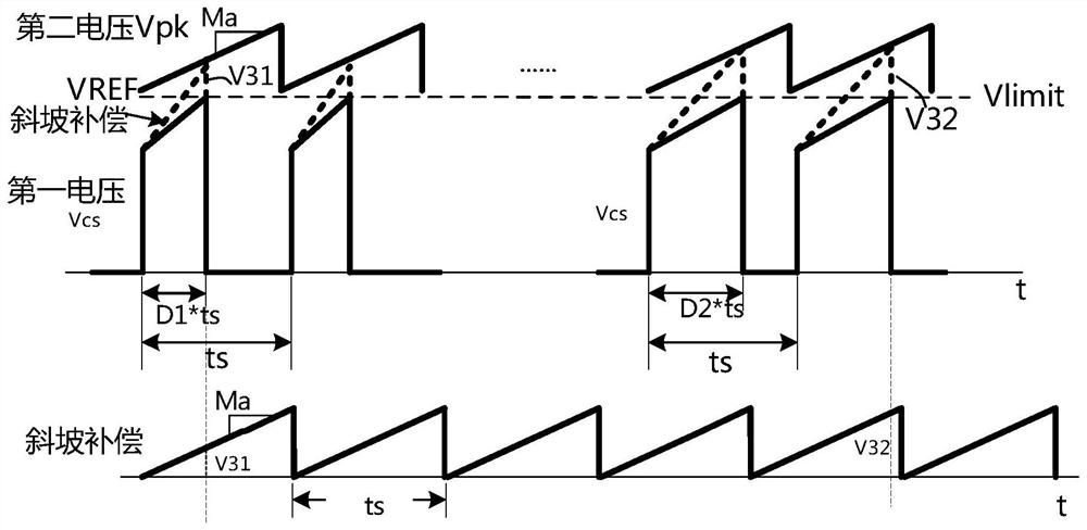
[0040] The overcurrent protection adopts a fixed reference voltage VREF, and the slope compensation applies a compensation signal with a slope of ma at the voltage corresponding to the inductor current. When the duty cycle of the inductor current is 25%, the compensation amount is added to the peak voltage signal corresponding to the peak value of the inductor current. V11, when the duty cycle of the inductor current is 50%, the compensation amount added to the peak voltage signal corresponding to the current peak value is V12, V12>V11, when VREF remains unchanged, the actual duty cycle is 50%. Peak V P less than the actual peak V at 25% duty cycle P , that is, in the ...


PUM


Abstract

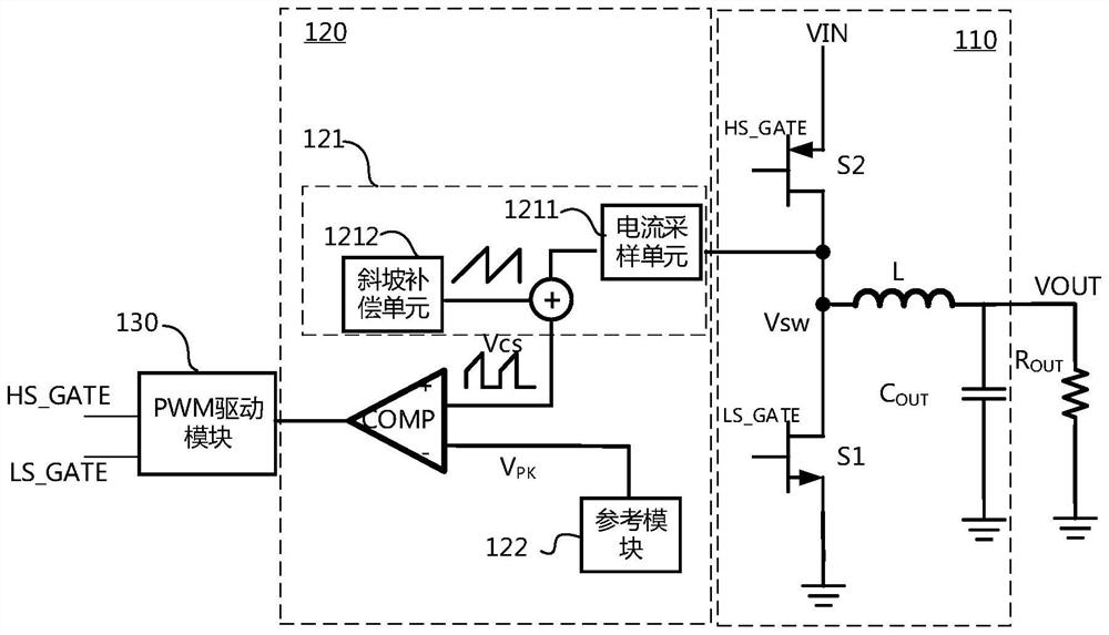
The present application discloses a device with overcurrent protection and an overcurrent protection method. The device includes: a DC-DC conversion circuit for converting a DC voltage, including an inductance; an overcurrent detection circuit, including a sampling module, coupled to to the DC-DC conversion circuit, for sampling the inductor current in the DC-DC conversion circuit, and generating a first voltage according to the inductor current; a reference module for generating a periodically changing second voltage, each The second voltage in one cycle gradually rises on the basis of a reference voltage; a comparator, the comparator has a first input terminal and a second input terminal, which are respectively coupled to the output terminals of the input module and the reference module , for comparing the first voltage with the second voltage to generate an overcurrent detection signal. The above device can keep the peak current of the inductor current stable.

Description

technical field [0001] The present application relates to the technical field of integrated circuits, and in particular, to an overcurrent protection device and an overcurrent protection method. Background technique [0002] A DC-DC converter is capable of changing an uncontrolled input DC voltage to another controlled output DC voltage. A DC-DC converter using current-controlled pulse-width modulation (PWM) is a commonly used converter that adjusts the output voltage by adjusting the pulse width to efficiently generate a rectified voltage output using power-free devices, including power switches , diode switches, inductors and capacitors and other devices. [0003] In the prior art, a fixed inductor current peak current threshold is usually used to limit the inductor current of the PWM-controlled DC-DC converter in the current control mode to prevent the chip from generating excessive heat or inductance due to excessive current. saturation and reduce the conversion effici...

Claims


Application Information

Patent Timeline
Patent Type & Authority Patents(China)
IPC IPC(8): H02M1/32H02M3/158H02M3/157H02M1/088
CPCH02M1/32H02M3/158H02M3/157H02M1/088H02M1/0029H02M1/0038H02M1/0009
Inventor 严之嶽袁政
Owner SHANGHAI AWINIC TECH CO LTD
Learn More