
Device and method for adjusting incident light intensity of imaging device, medium and equipment

A camera device and incident light technology, applied in image communication, color TV parts, TV system parts, etc., can solve problems such as adverse effects, blurred details, and affecting image clarity, so as to improve service life and improve Effects of improving quality and safety

Active Publication Date: 2020-12-25
BEIJING HORIZON ROBOTICS TECH RES & DEV CO LTD
View PDF10 Cites 1 Cited by
  • Summary
  • Abstract
  • Description
  • Claims
  • Application Information

AI Technical Summary

Problems solved by technology

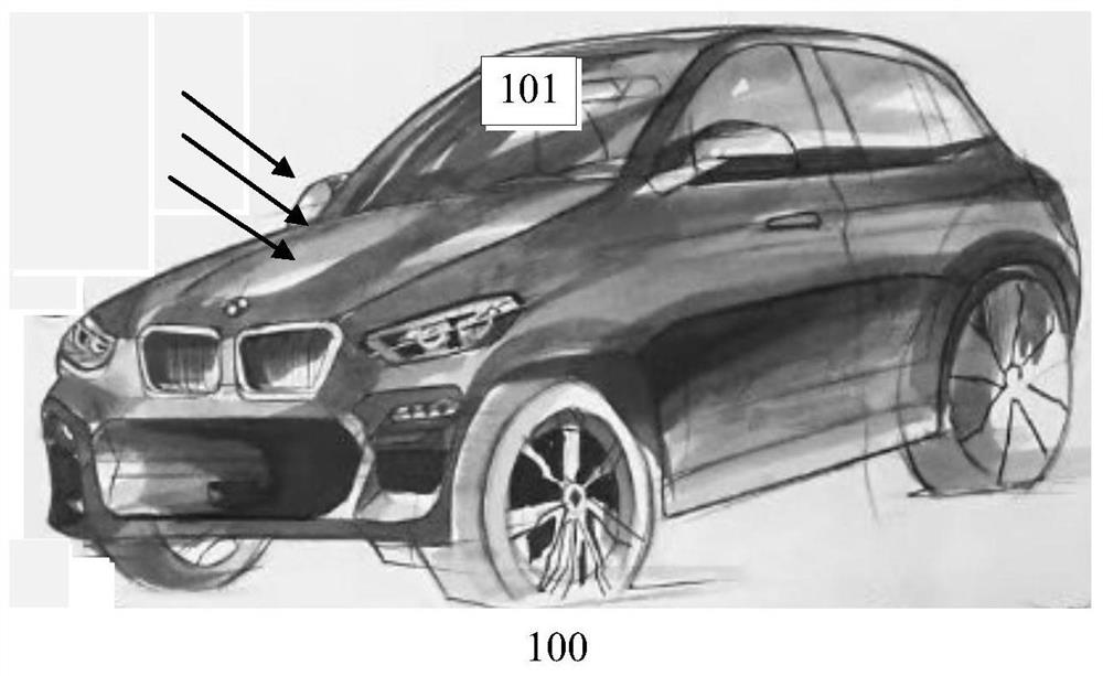
[0002] In the process of using the camera device, strong light will not only cause overexposure of the image collected by the camera device, but also affect the service life of the corresponding components in the camera device when the optical power reaches a certain level
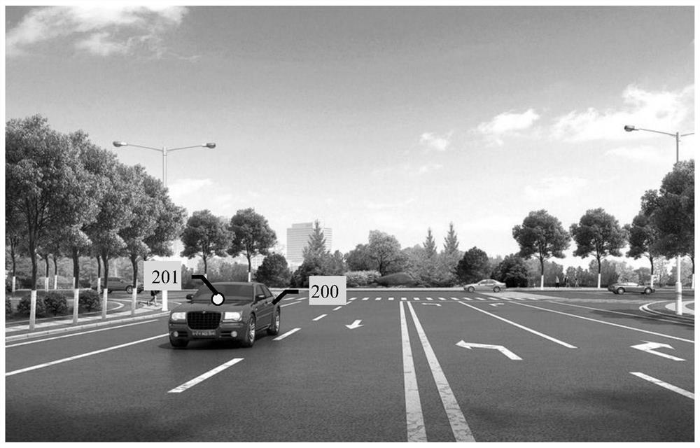
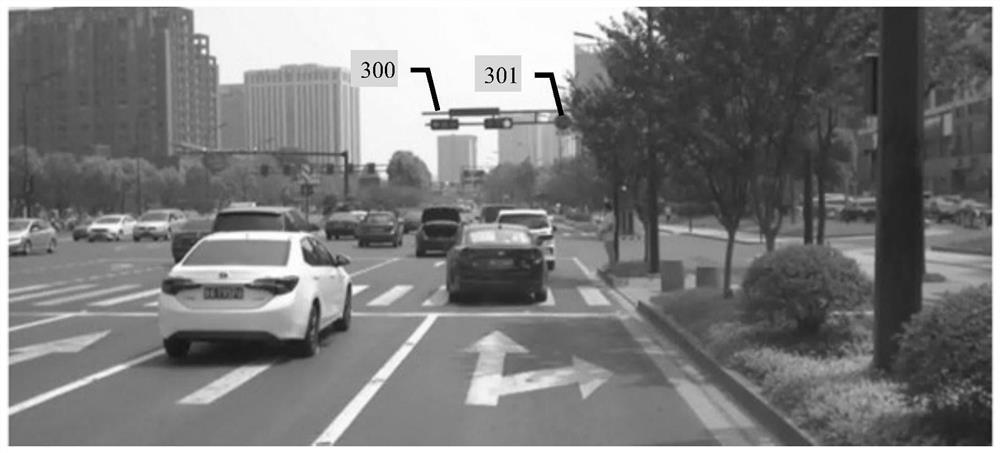
For the field of intelligent driving, because the overexposure phenomenon will affect the clarity of the image, such as the details in the image are blurred due to the highlight, etc., therefore, the strong light will also have a negative impact on the safety of the vehicle.

Method used


Image

  • Device and method for adjusting incident light intensity of imaging device, medium and equipment
  • Device and method for adjusting incident light intensity of imaging device, medium and equipment
  • Device and method for adjusting incident light intensity of imaging device, medium and equipment

Examples


Embodiment Construction

[0024] Example embodiments according to the present disclosure will be described in detail below with reference to the accompanying drawings. Apparently, the described embodiments are only some of the embodiments of the present disclosure, rather than all the embodiments of the present disclosure, and it should be understood that the present disclosure is not limited by the exemplary embodiments described here.

[0025] It should be noted that relative arrangements of components and steps, numerical expressions and numerical values ​​set forth in these embodiments do not limit the scope of the present disclosure unless specifically stated otherwise.

[0026] Those skilled in the art can understand that terms such as "first" and "second" in the embodiments of the present disclosure are only used to distinguish different steps, devices or modules, etc. necessary logical sequence.

[0027] It should also be understood that in the embodiments of the present disclosure, "plurality...


PUM


Abstract

The embodiment of the invention discloses a device and method for adjusting the incident light intensity of a camera device, a medium and equipment. The device comprises a shading part, a detection module and a control module, wherein the control module is connected with the shading part and the detection module; the shading part is arranged on the outer side of an optical lens of the camera device and comprises a first shading part and a second shading part. The detection module is used for detecting the incident light intensity of the camera device; and the control module is used for controlling the overlapping area of a light-transmitting region formed between the first shading part and the second shading part according to the incident light intensity detected by the detection module. The service life of the camera device can be prolonged, the quality of images shot by the camera device can be improved, and for the field of intelligent driving, the driving safety of vehicles can beimproved.

Description

technical field [0001] The present disclosure relates to image acquisition technology, and in particular, to a device for adjusting the incident light intensity of a camera device, a method for adjusting the incident light intensity of a camera device, a storage medium, and electronic equipment. Background technique [0002] In the process of using the camera device, the strong light will not only cause overexposure of the image collected by the camera device, but also affect the service life of the corresponding components in the camera device when the light power reaches a certain level. For the field of intelligent driving, because the overexposure phenomenon will affect the clarity of the image, such as the details in the image are blurred due to the highlight, etc., therefore, the strong light will also have a negative impact on the safety of the vehicle. Contents of the invention [0003] In order to solve the above-mentioned technical problems, the present disclosur...

Claims


Application Information

Patent Timeline
IPC IPC(8): H04N5/238H04N5/225
CPCH04N23/55H04N23/75
Inventor 董书成
Owner BEIJING HORIZON ROBOTICS TECH RES & DEV CO LTD
Learn More