Supercharge Your Innovation With Domain-Expert AI Agents!

Water conservancy construction safety facility

A technology for safety facilities and water conservancy, applied in the directions of roads, road signs, traffic signals, etc., can solve the problems of subsidence, soil density reduction, tilt, etc., to avoid the effect of removal

Inactive Publication Date: 2020-12-29
腾娟
View PDF13 Cites 6 Cited by
  • Summary
  • Abstract
  • Description
  • Claims
  • Application Information

AI Technical Summary

Problems solved by technology

[0003] Since the water conservancy ditch is slowly approaching the water source when the ditch is opened, the water source will slowly infiltrate into the soil of the ditch, which will reduce the density of the soil and sink. If the safety reflective cone for water conservancy construction is placed on the edge of the ditch, It is easy to follow the subsidence of the soil and appear inclined, which leads to the safety reflective cone of water conservancy construction is very vulnerable to the influence of natural slight wind and dumping

Method used


Image

  • Water conservancy construction safety facility
  • Water conservancy construction safety facility
  • Water conservancy construction safety facility

Examples


Embodiment 1

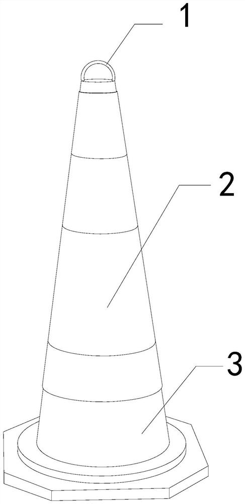
[0026]As for examplefigure 1 -exampleFigure 5 Shown:

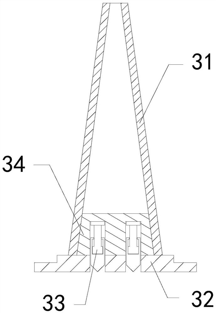
[0027]The present invention provides a safety facility for water conservancy construction. The structure includes a handle 1, a warning film 2, a bearing shell 3. The handle 1 is fixed at the upper end of the bearing shell 3, and the bearing shell 3 and the warning film 2 are Integrated structure; the carrying shell 3 includes an outer shell 31, a bottom plate 32, a sliding mechanism 33, an inner connecting plate 34, the bottom plate 32 is embedded in the bottom position of the shell 31, and the sliding mechanism 33 is installed at the inner position of the bottom plate 32 , The inner connecting plate 34 and the housing 31 are an integrated structure.

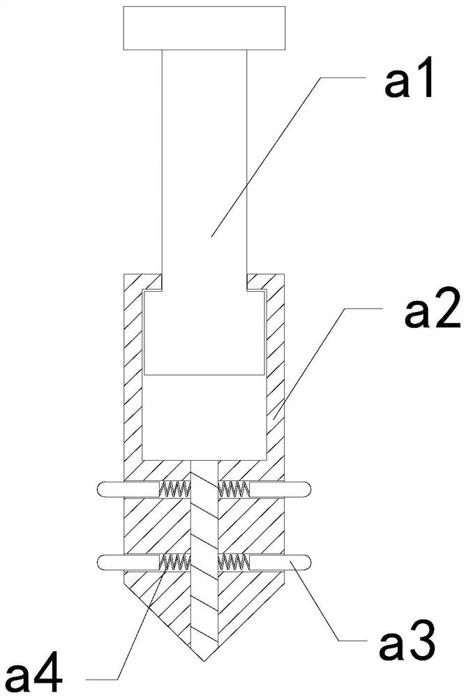
[0028]Wherein, the sliding mechanism 33 includes an engagement rod a1, an outer frame a2, an extension bar a3, and an elastic bar a4. The outer frame a2 is movably engaged with the engagement rod a1, and the extension bar a3 is in clearance fit with the outer frame a2. , The elastic st...

Embodiment 2

[0034]As for exampleFigure 6 -exampleFigure 8Shown:

[0035]Wherein, the grip increasing groove a35 includes a contact plate c1, a bottom plate c2, and a booster piece c3. The contact plate c1 is hingedly connected to the bottom plate c2, and the boost piece c3 is installed between the contact plate c1 and the bottom plate c2. At the same time, the vibration generated when the mechanism is contracted can make the contact plate c1 swing to the middle, so that the soil between the two contact plates c1 can be compacted.

[0036]Wherein, the contact plate c1 includes a water absorbing plate c11, an outer contact plate c12, and a receiving plate c13. The water absorbing plate c11 is movably engaged with the right side of the receiving plate c13, and the outer contact plate c12 is movably engaged with the right side of the water absorbing plate c11. For embedded connection, the water absorbing plate c11 is made of a corrosion-resistant and easy-to-clean polyether sponge material, and the water...


PUM


Abstract

The invention discloses a water conservancy construction safety facility. The water conservancy construction safety facility structurally comprises a lifting handle, a warning film and a bearing shell. The lifting handle is fixedly embedded in the upper end position of the bearing shell, and the bearing shell and the warning film are of an integrated structure. Soil placed in the bearing shell issoftened continuously by continuously permeating water into the soil, so that an outer frame is gradually inserted into the softened soil, and elastic strips can push extending strips which lose extrusion of the inner wall of a bottom plate to extend outwards, so that the extending strips generate high grabbing force to the interior of the soil under the cooperation of grabbing increasing grooves.A contact plate swings again to generate throwing force, so that a bearing plate slightly slides upwards and then resets to generate vibration, by cooperating with a separation block to extend outwards under the action of the throwing force, so that the separation block pushes the compacted soil outwards to be separated from the outer surface of the outer contact plate, and therefore the soil inthe grabbing increasing grooves can be easily removed.

Description

Technical field[0001]The invention relates to the field of water conservancy, in particular to a safety facility for water conservancy construction.Background technique[0002]Water conservancy construction safety reflective cones are mainly used to provide safety warnings when ditching water conservancy construction. By placing them around the trenches, they can prevent workers from slipping and falling. It is a common equipment for water conservancy construction. According to the above description, the inventor found that an existing water conservancy construction safety facility mainly has the following shortcomings, for example:[0003]As the water conservancy trench is slowly approaching the water source when the trench is opened, the water source will slowly infiltrate the soil in the trench, which will reduce the density of the soil and sink. If the water conservancy construction safety reflector is placed on the edge of the trench, It is easy to follow the sinking of the soil an...

Claims


Application Information

Patent Timeline
Patent Type & Authority Applications(China)
IPC IPC(8): E01F9/654E01F9/673
CPCE01F9/654E01F9/673
Inventor 腾娟
Owner 腾娟
Features
  • R&D
  • Intellectual Property
  • Life Sciences
  • Materials
  • Tech Scout
  • Unparalleled Data Quality
  • Higher Quality Content
  • 60% Fewer Hallucinations
Learn More