[0029] Next, the technical solutions in the embodiments of the present invention will be described in connection with the drawings of the embodiments of the present invention, and it is understood that the described embodiments are merely the embodiments of the present invention, not all of the embodiments. Based on the embodiments of the present invention, all other embodiments obtained by those of ordinary skill in the art are in the range of the present invention without making creative labor premise.
[0030] Further, the elements in the present invention are referred to as "fixed to" or "disposed to" another element, which can be directly in another element or may also present in place. When an element is considered to be "connected" another element, it can be directly connected to another element or may exist at the same time. The term "vertical", "horizontal", "horizontal", "left", "right", and similar expressions are merely illustrative, and the only embodiment is not shown.
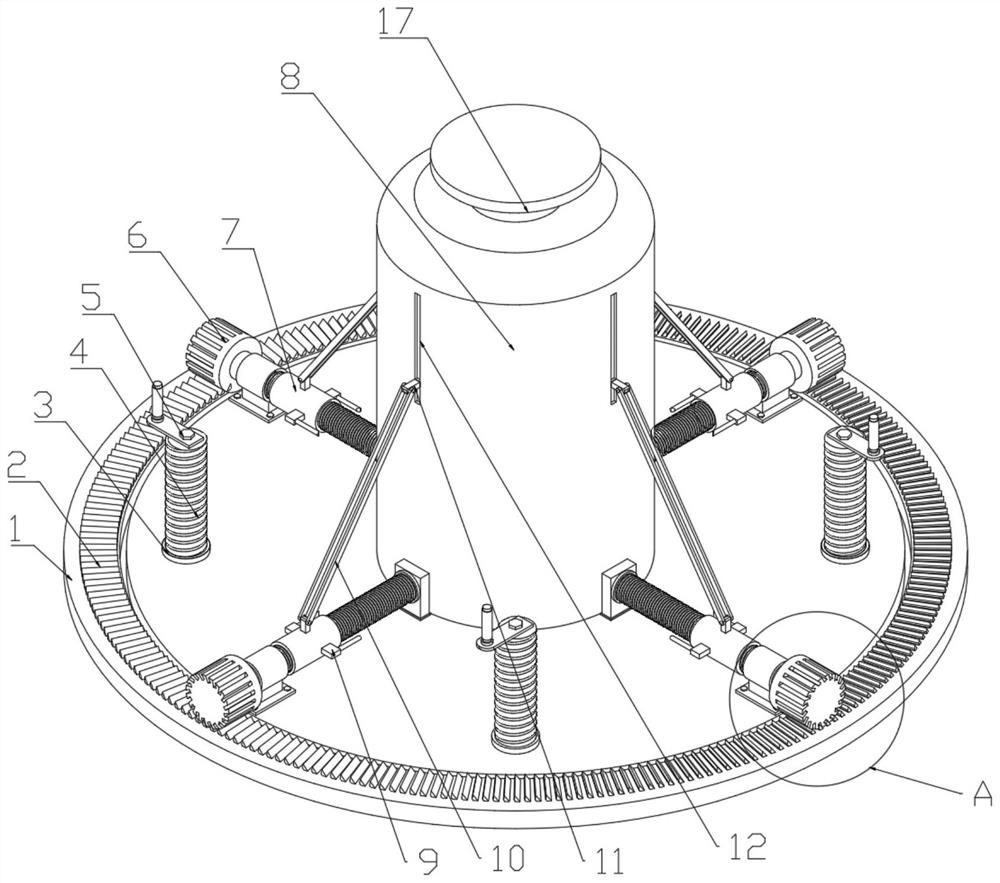
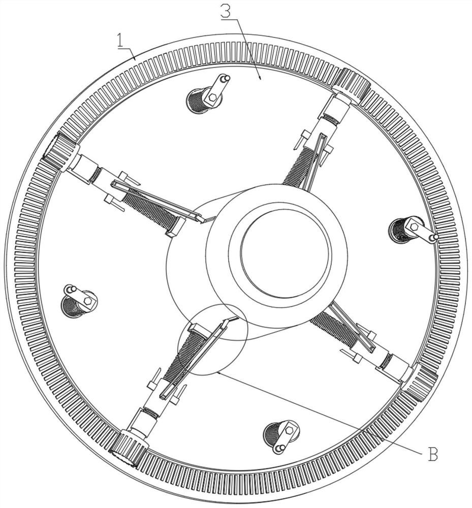
[0031] See Figure 1-4 In the embodiment of the present invention, a anti-pouring hydraulic jack, the anti-pouring hydraulic jack includes:
[0032] The transmission ring 1 is attached to the inner side of the transmission ring 1 lap by the sliding structure;
[0033] Jack 8, the jack 8 is mounted at the center of the underside, and the active end 8 is attached to the jack 8, and the jack 8 is also connected to the circumference distribution at least four groups at the eccentric part. The center of gravity dispersion mechanism is divided into the center of gravity of the jack 8 and the force end 17 when the center of gravity dispersion is operated.
[0034] The directional lifting structure is mounted at the bottom of the underside, the directional lifting structure for tilting it at any side when the receiving plate needs to be tilted.
[0035] In the embodiment of the present invention, the jack 8 is clamped in the center of gravity and disperse the center of gravity of the jack 8 to the underside, thereby enabling the jack 8 with ultra-high stability to be affected in the jack 8. The force will not be dumped under force;
[0036] And at the direction of directional lifting, it is possible to respond to the unminentable pavement or the jack 8 is in the inclined state to accommodate different occasions;
[0037] The stability and scene adaptability of this device are more prominent, and the size of the size can replace the existing common jack, wear the car, can be used when the vehicle needs to be repaired on various roads, and is unlimited.
[0038] In still another embodiment of the present invention, the gravity dispersion mechanism includes at least four movable grooves 12 on the outer side of the jack 8, the movable tank 12, in the inner sliding mounting of the moving tank 12 Bit block 16, the limit block 16 fixed to the movable block 11, the movable block 11 is connected to a gathering structure mounted on the receiving plate, the gathered structure being coupled to the synchronous transmission structure on the mounting plate.
[0039] In the embodiment of the present invention, the active block 11 and the restricted block 16 are vertically rising in the inner side of the movable tank 12 when the synchronous transmission structure operates, and the active block 11 and the restricted block 16 are vertically rising in the inner side of the movable tank 12, and move in the limit block 16 and the movable tank 12 to the stroke. At the end, the jack 8 is given to a relatively power, and the gravity of the gravity and the center of gravity are dispersed to the four sets of gathered structures at the force end 17 and 18. Therefore, it will not be poured due to the unstable center of gravity.
[0040] In still another embodiment of the present invention, the gathered structural packet rotates at least four first threaded rods mounted on the receiving plate, the first threaded rod outer thread having a second threaded sleeve 7, the first The two threaded sleeve 7 is hinged to the movable block 11 by hinged support rod 10, and the first threaded rod is also connected to the synchronous transmission structure.
[0041] The two sides of the second threaded sleeve 7 are fixedly mounted with two clamping rods for clamping the jack 8, the clamping rod 9 being inclined towards one side of the jack 8.
[0042] In the embodiment of the present invention, the first threaded rod is rotated in the synchronous transmission structure, driving the second threaded sleeve 7 horizontally during the first threaded rod, and passes the support rod when the second threaded sleeve 7 moves. 10 Plus the activity block 11 vertically rises, move the movable block 11 through the support rod 10 to move to the end of the stroke at the end of the second threaded sleeve 7, and simultaneously clamped by the bottom of the jack 8 through the second threaded sleeve 7. This ensures that the jack 8 is in a state where the center of gravity is dispersed.
[0043] In still another embodiment of the present invention, the synchronous transmission structure includes a plurality of inclined rack plates 2 disposed on the transmission ring 1, the inclined rack plate 2 engaged in the first mounting in the first The inclined gear 6 on the threaded rod.
[0044] In the embodiment of the present invention, the transmission ring 1 is rotated by an external force, and when the transmission ring 1 is rotated, the inclined rack plate 2 is rotated, and four tilt gears 6 are simultaneously rotated when the inclined rack 2 is rotated.
[0045] It should be noted that the inclined rack plate 2 and the inclined gear 6 are ralted teeth.
[0046]A further embodiment of the present invention, the lifting structure comprises a circumferential directional equally opens in the first plurality of the threaded sleeve receiving plate 3, the first inner threaded sleeve 3 is mounted with a screw connection the second threaded rod 4, the second threaded rod 4 is fixed to a handle 5 is mounted, and the threaded rod 4 away from the second side of the handle 5 is removably attached to the support plate 13.
[0047] In an embodiment of the present invention, by rotating the handle 5 is rotated to drive a second threaded rod 4, due to the presence of a first upstanding threaded sleeve 3 decreases or increases when rotation of the second threaded rod 4;
[0048] Whereby the uneven surface can be adapted through adjusting the second threaded rod 4, and a second threaded rod may also be adjusted when the need to tilt the jack 8 is placed so that the jack 4 to 8 to a suitable inclined position;
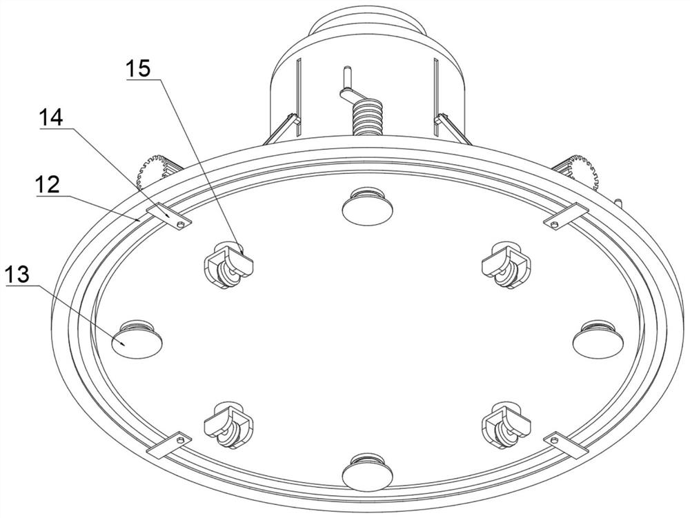
[0049] Support disk 13 may be mounted to increase the contact surface 6 inclined gear contact with the ground when the ground Jiaoruan used.
[0050] A further embodiment of the present invention, the slide structure includes a fixed plate mounted on the bottom of the receiving receiving block 14, the receiving block 14 12 defines a sliding fit with the bottom of the ring gear 1 moving groove to the drive when ring 1 is rotated without receiving the holder plate.
[0051] In an embodiment of the present invention, upon rotation of the drive ring is 1 on the receiving block 14 for receiving the drive block 14 functions for receiving a ring;
[0052] It may also be provided toward a side of the slider receiving plate 1 in the drive ring, sliding in the opening receiving plate, so that a sliding fit, the specific method can be selected according to needs.
[0053] A further embodiment of the present invention, the receiving plate having at least a bottom peripheral laid four casters 15 for movement.
[0054] In an embodiment of the present invention, the caster 15 may be performed in a smooth road push, when using a second threaded rod 4 is not in contact with the ground, is not in contact with the ground when the second threaded rod 4 is in contact with the ground.
[0055] A further embodiment of the present invention, the receiving further outer plate fixedly attached to the protective housing for protecting the user.
[0056] In an embodiment of the present invention, the safety ensuring device shell may not cause harm to the user during exercise, and to improve the appearance and handle may be detachably mounted on the bottom push receiving plate to the header length is not enough when the present apparatus may be pushed to a specified position (not shown).
[0057] It is apparent to those skilled in the art that the present invention can be implemented in other specific forms without departing from the spirit or essential characteristics of the present invention without departing from the spirit or essential characteristics of the present invention. Therefore, in any case, it should be regarded as an exemplary, and non-limiting, and the scope of the invention is defined by the appended claims. Therefore, it is intended to fall in accordance with the claims All changes in the meaning and range of equivalents are included in the present invention. Any reference numerals in the claims should not be regarded as the claims.
[0058] In addition, it should be understood that although this specification describes in accordance with an embodiment, it is not to include only one independent technical solution, and this description of the specification is simply, and those skilled in the art should use the specification as a whole. The technical solutions in each of the examples may also be appropriately combined to form another embodiments which will be appreciated by those skilled in the art.