
Rigidity compensation device, harmonic reducer and robot

A technology of harmonic reducer and compensation device, which is applied in the direction of transmission, transmission parts, mechanical equipment, etc., and can solve the problems affecting the transmission accuracy of harmonic reducer and unfavorable overall performance.

Active Publication Date: 2020-12-29
GREE ELECTRIC APPLIANCES INC
View PDF9 Cites 1 Cited by
  • Summary
  • Abstract
  • Description
  • Claims
  • Application Information

AI Technical Summary

Problems solved by technology

[0004] In the prior art, the contact area is enlarged and the rigidity of the harmonic reducer is improved by replacing the common cross-roller bearing with the ballless bearing formed by the combination of the support sleeve and the support shaft, but this method changes the rigid bearing part to The dynamic fit of the supporting sleeve and the supporting shaft, changing the friction form between the parts, will directly affect the transmission accuracy of the harmonic reducer, which is not conducive to the improvement of the overall performance

Method used


Image

  • Rigidity compensation device, harmonic reducer and robot
  • Rigidity compensation device, harmonic reducer and robot
  • Rigidity compensation device, harmonic reducer and robot

Examples


Embodiment Construction

[0031] The following will clearly and completely describe the technical solutions in the embodiments of the present invention with reference to the drawings in the embodiments of the present invention. Apparently, the described embodiments are only some of the embodiments of the present invention, but not all of them. The following description of at least one exemplary embodiment is merely illustrative in nature and in no way taken as limiting the invention, its application or uses. Based on the embodiments of the present invention, all other embodiments obtained by persons of ordinary skill in the art without creative efforts fall within the protection scope of the present invention.

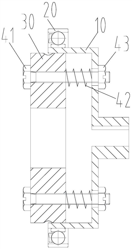
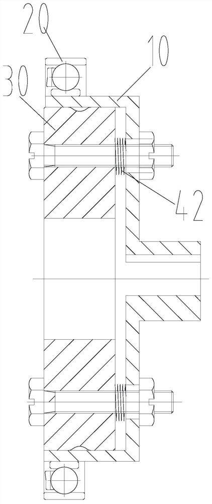
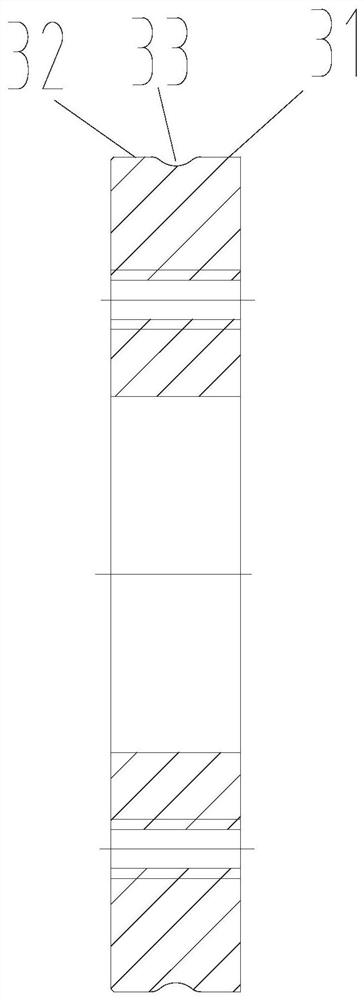
[0032] like Figure 1 to Figure 9 As shown, the embodiment of the present invention provides a stiffness compensation device, comprising: a flexible cup 10, the flexible cup 10 has a receiving chamber; a flexible bearing 20, set on the flexible cup 10; Moveably arranged in the accommodation c...


PUM


Abstract

The invention provides a rigidity compensation device, a harmonic reducer and a robot. The rigidity compensation device comprises a flexible cup sleeve, a flexible bearing and a cam body, wherein theflexible cup sleeve is provided with a containing cavity; the flexible cup sleeve is sleeved with the flexible bearing; and the cam body is arranged in the containing cavity in an axially movable mode, the cam body is provided with a plurality of outer circumferential faces with different shapes in the axial direction of the cam body, and each outer circumferential face is selectively arranged corresponding to the flexible bearing so as to adjust the radial deformation amount of the flexible bearing. Due to the fact that the cam body is provided with the outer circumferential faces with different shapes, after the different outer circumferential faces move to the position corresponding to the flexible bearing, the radial deformation amount of the flexible cup sleeve and the flexible bearing can be changed, that is, the deformation degree of the flexible bearing is changed; and the deformation degree of the flexible gear can be changed by changing the deformation degree of the flexiblebearing, so that the number of pairs of meshing teeth and the size of a meshing area of a rigid-flexible gear can be increased by changing the deformation degree of the flexible gear after rigid-flexible gear teeth of the harmonic reducer are abraded, the torsional rigidity of the harmonic reducer is improved, and the service life of the harmonic reducer is prolonged.

Description

technical field [0001] The invention relates to the technical field of harmonic reducers, in particular to a stiffness compensation device, a harmonic reducer and a robot. Background technique [0002] The harmonic reducer is mainly composed of a rigid wheel, a flexible wheel and a wave generator, and the wave generator is composed of a cam with a special curved profile and a flexible bearing. During the movement, the long axis of the cam will force the flexible bearing and the flexible spline to produce controllable radial elastic deformation. The flexible spline and the rigid spline mesh with each other to transmit motion and power. When it is enough to eliminate the backlash between adjacent tooth pairs, multi-tooth meshing is formed, and the number of multi-tooth meshing depends on the backlash distribution between the gear teeth in the assembled state and the elastic deformation of the flexspline under the action of meshing force. [0003] The number of multi-teeth mes...

Claims


Application Information

Patent Timeline
IPC IPC(8): F16H49/00F16H57/021F16H57/02
CPCF16H49/001F16H57/021F16H57/02
Inventor 钟成堡杨繁荣谷甲甲程中甫田珍珍吴婷婷
Owner GREE ELECTRIC APPLIANCES INC
Learn More