
A microwave field type wireless charging device

A wireless charging and microwave field-type technology, which is applied to circuit devices, battery circuit devices, current collectors, etc., can solve problems such as low charging efficiency, low charging efficiency, and different voltage platforms and charging interfaces, so as to save energy and improve The effect of charging efficiency

Active Publication Date: 2022-06-21
军事科学院系统工程研究院军事新能源技术研究所
View PDF3 Cites 0 Cited by
  • Summary
  • Abstract
  • Description
  • Claims
  • Application Information

AI Technical Summary

Problems solved by technology

[0002] At present, most electronic devices use wired charging. The disadvantage is that the charging process relies on cables, and there is a risk of wire contact and frictional discharge. The voltage platform and charging interface are different, resulting in a complicated charging process and low charging efficiency.
This will lead to low charging efficiency, and the charging environment is exposed to free space, and the safety cannot be guaranteed

Method used


Image

  • A microwave field type wireless charging device
  • A microwave field type wireless charging device
  • A microwave field type wireless charging device

Examples


Embodiment 1

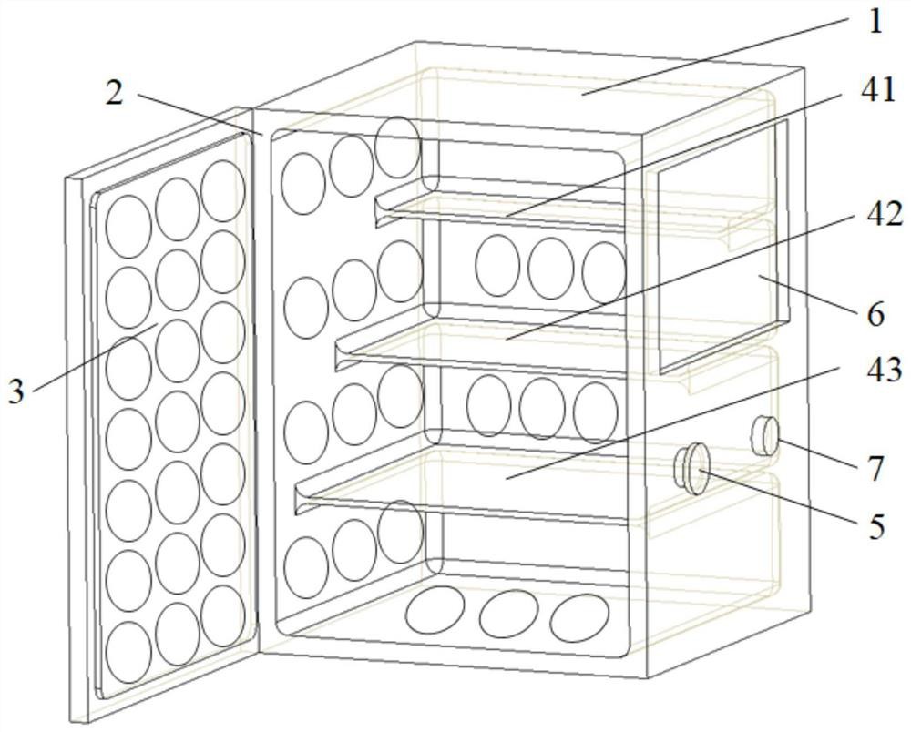
[0084] see figure 1 , figure 1 It is a schematic structural diagram of a microwave field type wireless charging device provided by an embodiment of the present invention. like figure 1 As shown, the device includes a casing 1, a cavity 2, a microwave signal source ( figure 1 not shown), power amplifier ( figure 1 not shown in), the transmitting antenna 3, the partition plate and the switch button 5 placed on the surface of the casing 1, the position acquisition module ( figure 1 not shown in) and the control module ( figure 1 not shown), wherein,

[0085] The cavity 2 has a box-type structure and is placed inside the casing 1 . When the cabinet door of the cavity 2 is closed, the casing 1 is used to shield the magnetic field in the cavity 2 . Wherein, the casing may be made of metal. The interior of the cavity is designed without edges and corners, that is, the circumference of the cavity and the contact points of the partition are rounded.

[0086] The separator is ar...

Embodiment 2

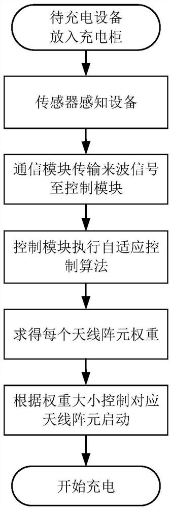
[0123] see Figure 8 , Figure 8 It is a schematic flowchart of a microwave field type wireless charging control method provided by an embodiment of the present invention. The method is applied to the charging process of the above-mentioned microwave field type wireless charging device, and can be executed by a control module in the microwave field type wireless charging device. like Figure 8 As shown, the charging control method provided by this embodiment specifically includes:

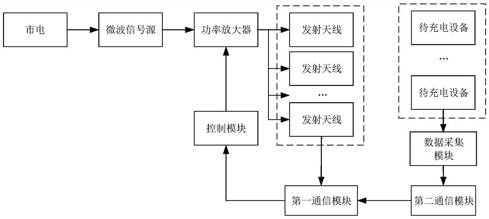
[0124] 110. Receive the position data of each device to be charged, and control the activation of the transmitting antenna at the corresponding position according to the position data.

[0125] Wherein, the transmitting antenna includes a plurality of antenna array elements arranged in the form of an array; the position data of the device to be charged can be obtained by a position sensor.

[0126] 120. Determine the weight of each antenna element in the activated transmit antenna.

[0127] Ex...


PUM


Abstract

The embodiment of the present invention discloses a microwave field type wireless charging device, wherein the device includes: a housing, a cavity, a microwave signal source, a power amplifier, a transmitting antenna, a partition and a switch button, wherein the cavity has a box-like structure , placed inside the casing, when the cabinet door of the cavity is closed, the casing is used to shield the magnetic field in the cavity; the partitions are arranged inside the cavity in a stepped layered structure, and are used to place the equipment to be charged; the microwave signal source It is placed inside the cavity and is used to convert the electrical signal received by the cavity into a microwave signal when the switch button is triggered; the power amplifier is used to amplify the power of the microwave signal; the transmitting antenna is placed on the inner wall of the cavity for After starting up, the power amplified microwave signal is radiated to the inside of the cavity, and the receiving device of the device to be charged receives the power amplified microwave signal to charge the device to be charged. By adopting the above technical solution, the charging efficiency is improved while ensuring the charging safety.

Description

technical field [0001] Embodiments of the present invention relate to the technical field of wireless charging, and in particular, to a microwave field type wireless charging device. Background technique [0002] At present, most electronic devices use wired charging. The disadvantage is that the charging process relies on cables, there is the danger of wire contact and frictional discharge, and the voltage platform and charging interface are different, resulting in complicated charging process and low charging efficiency. The wireless charging realizes the energy transmission between the power supply and the electrical equipment in a non-contact wireless way. The emergence of wireless charging technology makes up for the defects of wired charging. [0003] In the current microwave wireless charging products, when the microwave energy transmission method is used for wireless charging, the antenna array can only be activated at the same time to charge the device to be charged...

Claims


Application Information

Patent Timeline
Patent Type & Authority Patents(China)
IPC IPC(8): H02J7/02H02J50/00H02J50/20H02J50/80
CPCH02J7/02H02J50/005H02J50/20H02J50/80
Inventor 徐万里王长富鲁长波王旭东周友杰刘盼盼李施展陈今茂安高军李华徐曦萌孙彦丽
Owner 军事科学院系统工程研究院军事新能源技术研究所
Learn More