Self-locking walking machine capable of preventing overspeed rotation

A walking machine and self-locking technology, applied in sports accessories, training equipment for adjusting coordination, training equipment for adjusting cardiovascular system, etc. Self-locking and other problems can improve safety, prevent people from falling, and prevent thighs from being pulled.

Active Publication Date: 2021-01-01
台州市博跃塑业有限公司
View PDF5 Cites 1 Cited by
  • Summary
  • Abstract
  • Description
  • Claims
  • Application Information

AI Technical Summary

Problems solved by technology

[0005] Aiming at the deficiencies of the prior art, the present invention provides a walker that prevents over-rotation and is self-locking, which can be self-locking when no one is using it, preventing children from being injured by swinging the pedals, and preventing over-speeding during use. The advantage of fast swing is to prevent people from straining their legs due to the over-speed swing of the pedals when they are in use, and to avoid people falling due to imbalance. It solves the problem that the walker cannot be self-locked when it is not in use. Children will push the pedals due to curiosity Children will be injured when swinging back, and the walking machine cannot prevent over-speed swinging. When the force is too large, the thighs of the person will be pulled due to the inertia of the pedal, resulting in injury, and because of the excessive inertia, the person will lose balance and fall the problem of the situation

Method used


Image

  • Self-locking walking machine capable of preventing overspeed rotation
  • Self-locking walking machine capable of preventing overspeed rotation
  • Self-locking walking machine capable of preventing overspeed rotation

Examples


Embodiment Construction

[0027] The following will clearly and completely describe the technical solutions in the embodiments of the present invention with reference to the accompanying drawings in the embodiments of the present invention. Obviously, the described embodiments are only some, not all, embodiments of the present invention. Based on the embodiments of the present invention, all other embodiments obtained by persons of ordinary skill in the art without making creative efforts belong to the protection scope of the present invention.

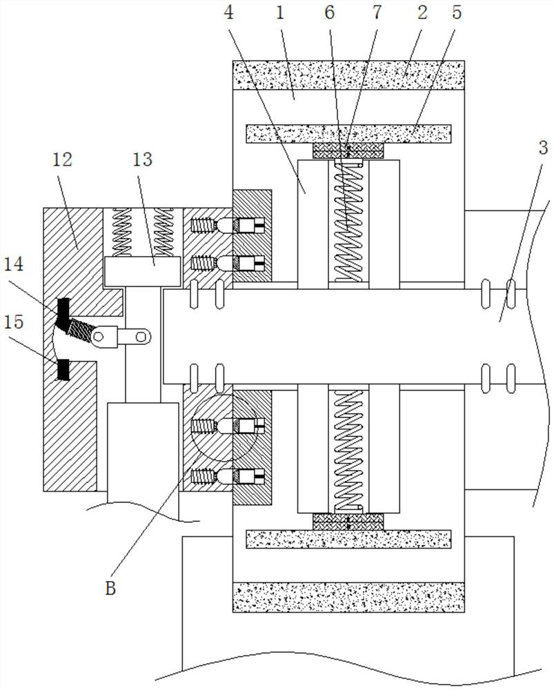
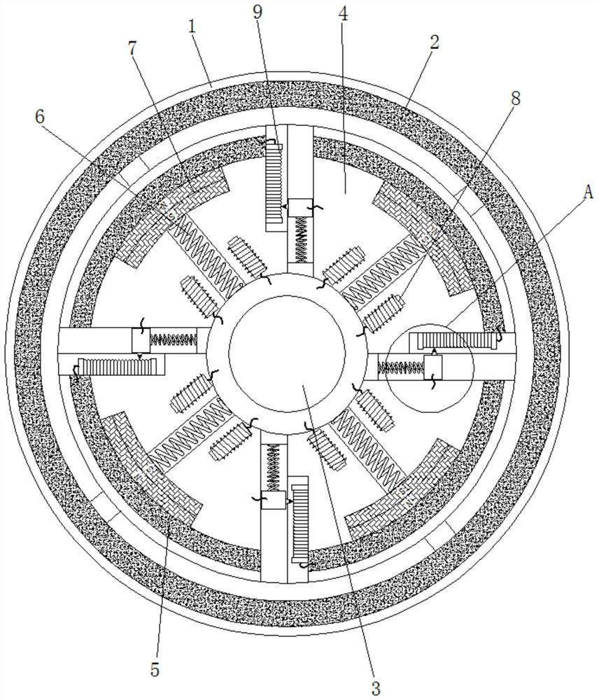
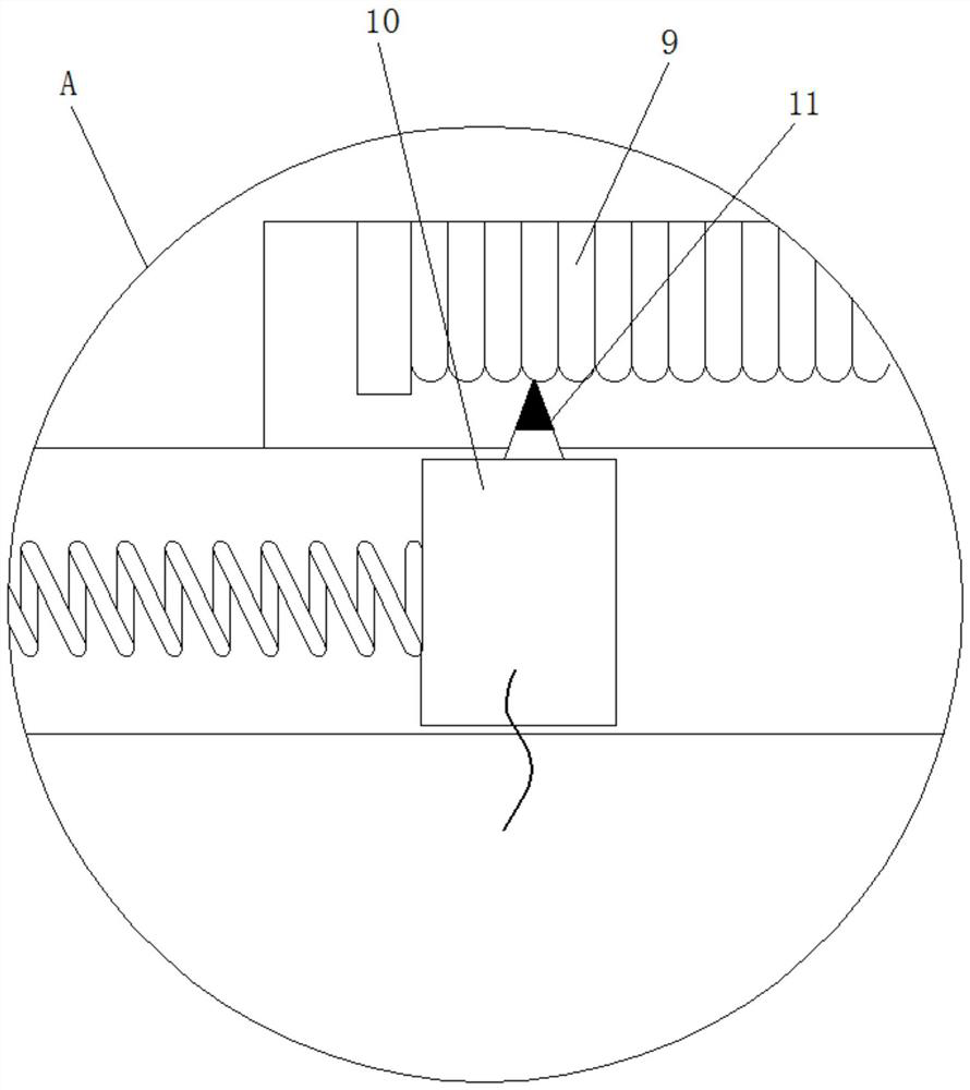
[0028] see Figure 1-6 , a self-locking walker that prevents overspeed rotation and includes a fixed frame 1, the lower end of the fixed frame 1 is fixedly connected to a base, and the base is fixedly connected to the ground. The inner surface of the fixed frame 1 is fixedly connected with a friction plate 2, and the inside of the fixed frame 1 is connected with a rotating shaft 3 for rotation, and a fixed pin is fixedly connected between the rotating shaft 3 ...


PUM


Abstract

The invention relates to the technical field of fitness equipment, and discloses a self-locking walking machine capable of preventing overspeed rotation, which comprises a fixing frame, a friction plate is fixedly connected to the inner surface of the fixing frame, a rotating shaft is rotatably connected to the interior of the fixing frame, and a rotating disc is fixedly connected to the surface of the rotating shaft; a pressing plate is slidably connected to the interior of the rotating disc, a reset spring is fixedly connected to the bottom of the pressing plate, a magnetic block is fixedlyconnected to the lower end of the pressing plate, an electromagnetic column is fixedly connected to the interior of the rotating disc, and a resistance strip is fixedly connected to the surface of therotating disc. A trigger rod on the surface of a sliding rod is connected with the upper end of a metal strip, so that a rotating column can be fixedly connected with a fixing frame through a stop block, and the effects that automatic locking can be achieved when no person uses the walking machine, a child is prevented from pushing the pedal with hands, the child is protected from being injured by the pedal, and the using safety is improved are achieved.

Description

technical field [0001] The invention relates to the technical field of fitness equipment, in particular to a walking machine capable of preventing excessive rotation and being capable of self-locking. Background technique [0002] Fitness equipment is installed in every community, and it is used by a wide range of people. Among them, the walking machine is very popular, but the walking machine cannot be self-locked when it is not in use. Children will push the pedals due to curiosity, and the pedals will swing back when they swing back. Injury to children, and the walking machine cannot prevent over-speed swinging. When the force is too large, the thighs of the person will be pulled due to the inertia of the pedals, resulting in injury, and the person will lose balance and fall due to the excessive inertia. [0003] In order to solve the above problems, the inventor provides a walking machine that prevents over-rotation and is self-locking. The trigger lever on the surface o...

Claims


Application Information

Patent Timeline
Patent Type & Authority Applications(China)
IPC IPC(8): A63B22/04
CPCA63B22/04
Inventor 张志辉
Owner 台州市博跃塑业有限公司
Why Eureka
Try Eureka