A kind of cow hair removal device for leather processing

A cow hair and leather technology, which is applied in raw hide/leather/fur manufacturing equipment, leather manufacturing, small raw hide/big raw hide/leather/fur treatment, etc. It can solve problems such as laborious and difficult to scrape off the cow hair

Active Publication Date: 2022-02-18
温州国仁皮业有限公司
View PDF6 Cites 0 Cited by
  • Summary
  • Abstract
  • Description
  • Claims
  • Application Information

AI Technical Summary

Problems solved by technology

[0005] In order to overcome the shortcoming that it is necessary to constantly move the hand to make the scraping tool scrape off the cow hair, it takes a long time and it is laborious, and because the force of each scraping is not the same, it is difficult to scrape off some cow hair. The technical problem is as follows: A cow hair removal device for leather processing that can replace manual scraping of cow hair, is relatively labor-saving, and can completely scrape the cow hair clean

Method used


Image

  • A kind of cow hair removal device for leather processing
  • A kind of cow hair removal device for leather processing
  • A kind of cow hair removal device for leather processing

Examples


Embodiment 1

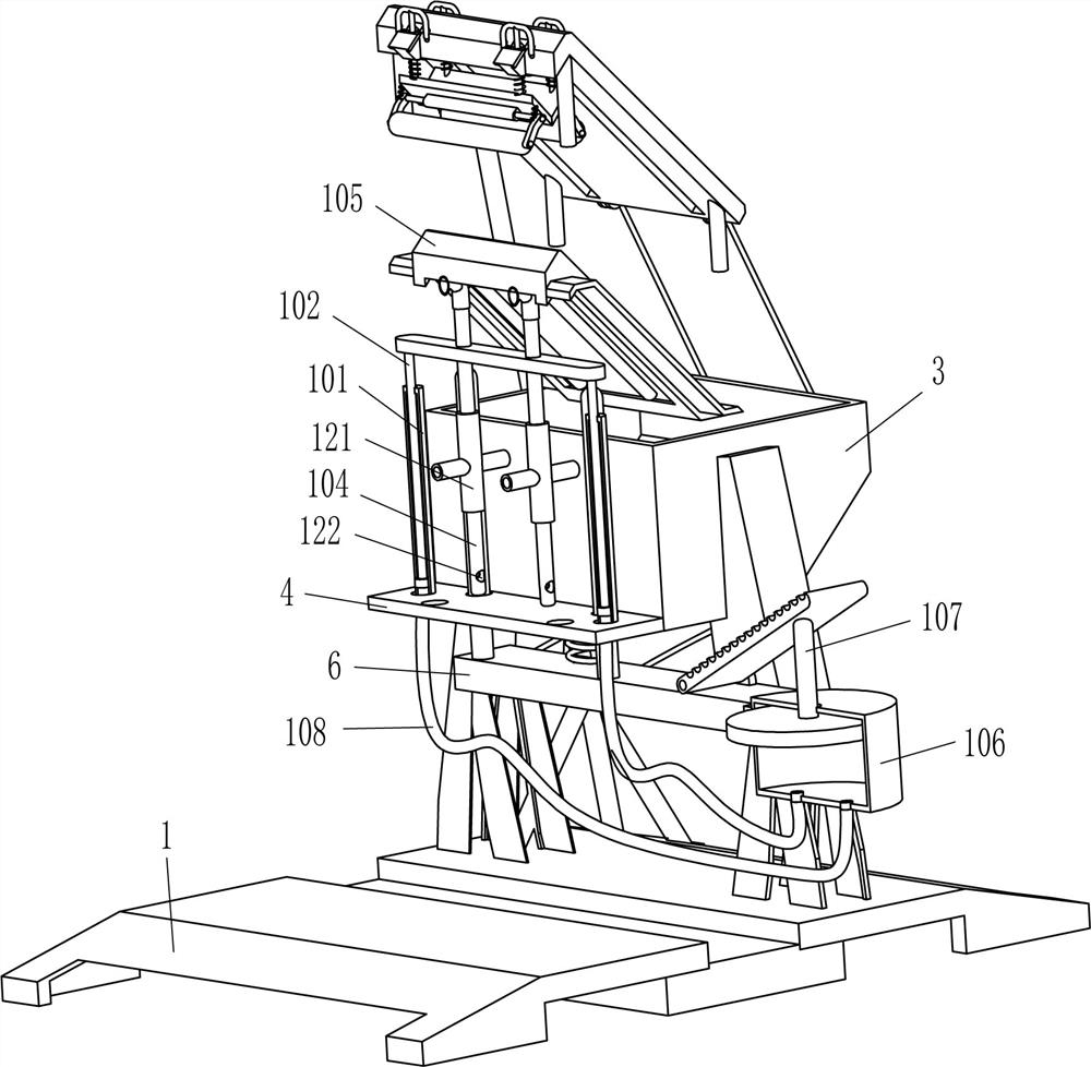
[0023] A kind of cow hair removal device for leather processing, such as Figure 1-Figure 4 As shown, it includes a base 1, a support plate 2, a collection frame 3, a mounting plate 4, a guide rod 5, a movable plate 6, an elastic member 61, a pedal 7, a bracket 8, an L-shaped plate 9, a placement mechanism 10 and a scraping mechanism 11. Support plates 2 are fixed symmetrically on the front and rear sides of the top of the base 1, and the collection frame 3 is fixed between the upper inner surfaces of the two left support plates 2 and the upper inner surfaces of the two right support plates 2 A mounting plate 4 is fixedly connected between the lower part of the outer right side of the left collecting frame 3 and the lower part of the outer left side of the right collecting frame 3, and the front and rear parts of the mounting plate 4 are all symmetrically slidable and connected with guide rods 5 A movable plate 6 is fixedly connected between the bottom ends of the two guide ro...

Embodiment 2

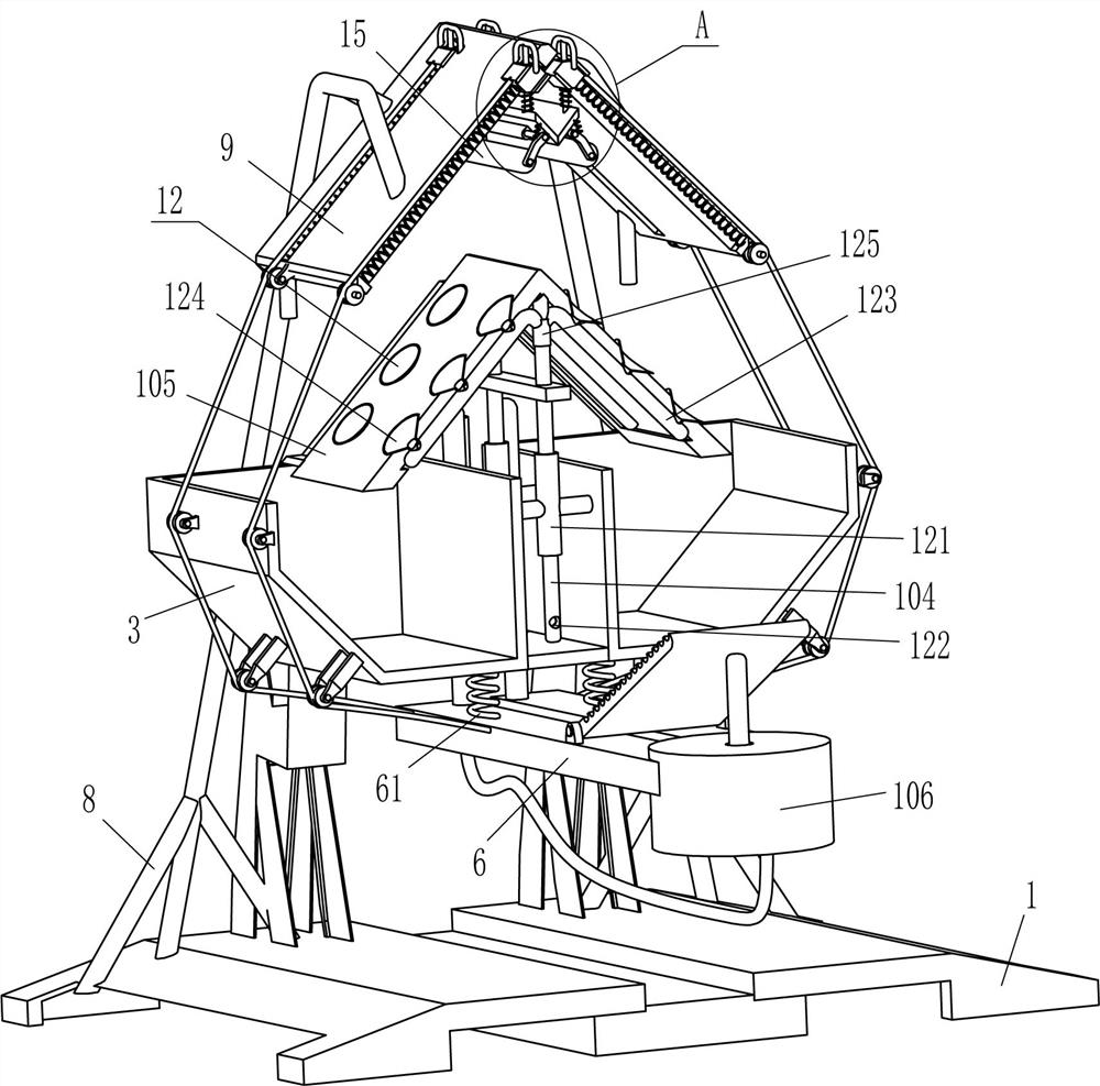
[0030] On the basis of Example 1, such as figure 2 As shown, it also includes a fixing mechanism 12, the fixing mechanism 12 includes a fixing sleeve 121, an air outlet pipe 123, a suction cup 124 and a sleeve pipe 125, and the outer right side of the left collection frame 3 and the outer left side of the right collection frame 3 A fixed sleeve 121 is fixed symmetrically between the upper parts, and the hollow rod 104 slides through the fixed sleeve 121 to fit with it. The upper part of the hollow rod 104 is fixed with a sleeve 125, which communicates with the hollow rod 104, and the L-shaped placement plate Both sides of the left and right sides in 105 are fixedly connected with air outlet pipe 123 symmetrically front and back, the inner end of air outlet pipe 123 is fixedly connected and communicated with sleeve pipe 125, and the left and right sides of the L-shaped placing plate 105 are all evenly spaced with suction cups 124 fixedly connected therein. The end is connected...

Embodiment 3

[0033] On the basis of embodiment 1 and embodiment 2, such as figure 1 , figure 2 and Figure 4 As shown, it also includes a rubber rod 13 and an L-shaped contact plate 14. The L-shaped contact plate 14 is fixedly connected to the front and rear sides of the L-shaped placement plate 105. Rod 13, in the middle of the top of L-shaped plate 9, also is fixedly connected with rubber rod 13 symmetrically front and back, and rubber rod 13 cooperates with L-shaped contact plate 14.

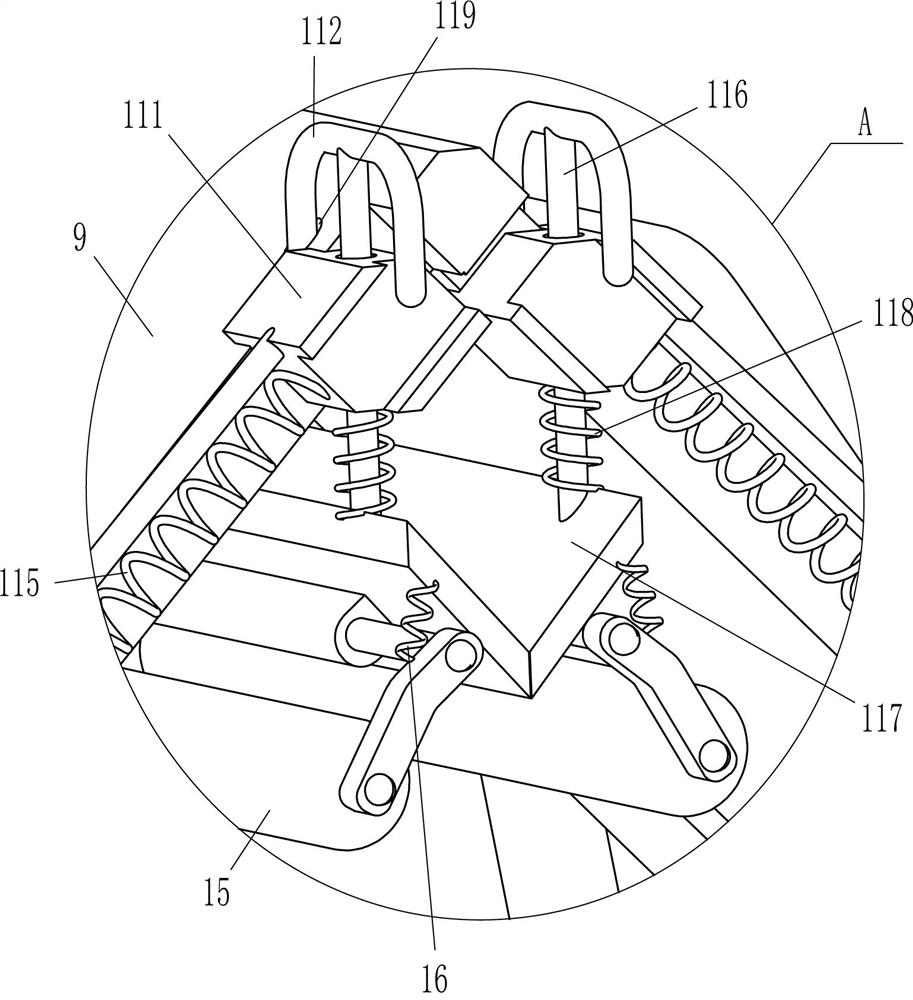
[0034] It also includes a pressure roller 15 and a third spring 16, the middle part of the outer surface of the scraper 117 is rotatably connected with the pressure roller 15, and the third spring 16 is connected between the front and rear sides of the outer side of the pressure roller 15 and the front and rear sides of the scraper 117.

[0035] When the L-shaped placement plate 105 moved upwards, the L-shaped placement plate 105 also drove the L-shaped contact plate 14 to move upwards, and the L-shape...


PUM


Abstract

The invention relates to a removal device, in particular to a cow hair removal device for leather processing. The technical problem is how to design a cow hair removal device for leather processing, which can replace the manual scraping of cow hair, save labor, and completely remove cow hair. A cow hair removal device for leather processing, comprising: a base, four support plates are fixedly fixed on one side of the base at intervals; a collection frame, the collection frame is fixed to two of the supports on each side away from the base between the sides of the board. In the present invention, the cowhide is placed on the L-shaped placing plate, the smooth side is in contact with the L-shaped placing plate, and the pedal is stepped on to swing downward, so that the L-shaped placing plate can drive the cowhide to contact the scraper, and continue to step on the pedal to move toward the scraper. The downward movement drives the movable plate to move downward, and the scraper moves downward to scrape off the cow hair. In this way, there is no need to manually scrape the cow hair, which is relatively labor-saving, and the cow hair can be scraped clean.

Description

technical field [0001] The invention relates to a removing device, in particular to a cow hair removing device for leather processing. Background technique [0002] Leather is denatured and non-perishable animal skin obtained through physical and chemical processing such as depilation and tanning. Leather is composed of natural protein fibers tightly woven in three-dimensional space. There is a special grain layer on the surface, which has natural grain and luster, and feels comfortable. During the leather processing process, the cow hair on the cowhide needs to be scraped off. To facilitate subsequent processing into leather. [0003] At present, most of the cowhide is manually scraped off the cowhide. First, people put the cowhide on a designated position, and then use a scraping tool to scrape off the cowhide. Because there are more cowhide, it is necessary to move the hand continuously. It takes a long time for the scraping tool to scrape off the cow hair, which is lab...

Claims


Application Information

Patent Timeline
Patent Type & Authority Patents(China)
IPC IPC(8): C14B1/04C14B1/30C14B17/08
CPCC14B1/04C14B1/30C14B17/08
Inventor 余秀民
Owner 温州国仁皮业有限公司
Why Eureka
Try Eureka